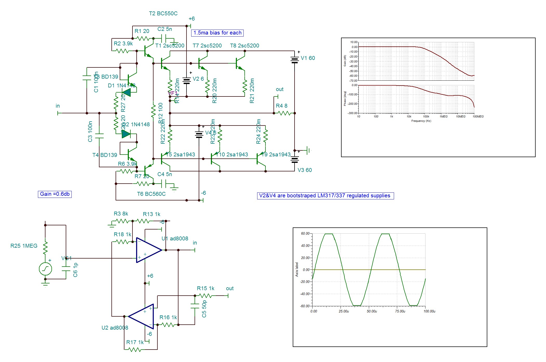
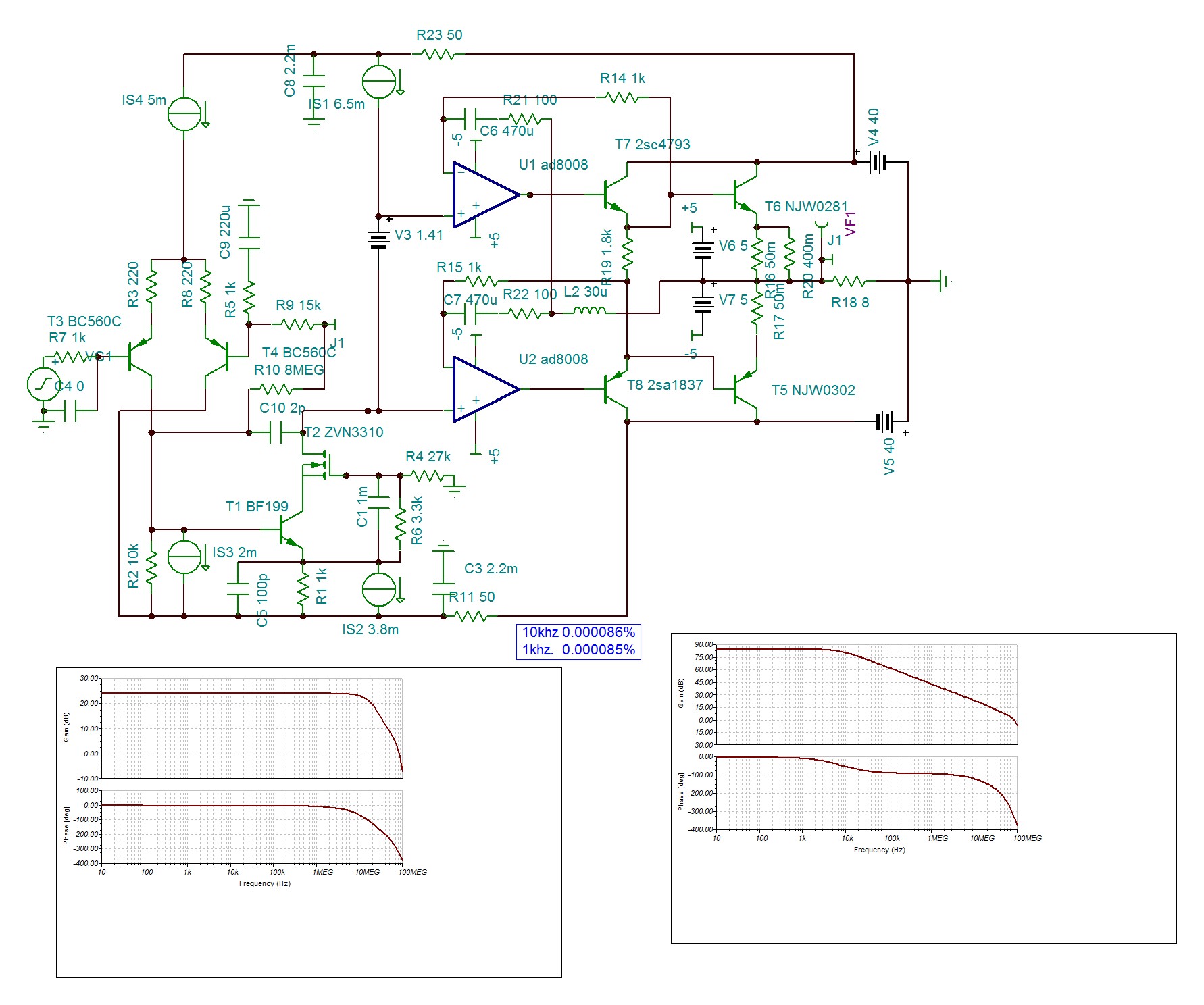
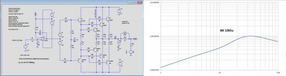
This topology uses a pair of floating power supply to drive the power outputs. By using low voltage higher performance components simpler and better amp can be obtained. It can be a UHF jfet bf256A driving the pilots(bc550C/560C) that each output can have it's own forcibly if they are MOSFETs . Low voltage op amp can also be used instead of jfet to provide some extra gain of 0.6db , to allow the VAS some +/-6v dropout while driving the output rail to rail excursion with the same PSU. The op amp can also be transformed into reactor to function as Hawksford error corrector which allows class B operation with very low distortion and extended frequency response. The circuit bellow can be submitted to 60db NFB at 20Khz .
Attachments
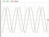
This is simpler and far lower distortion 200w /8ohm version . The distortion at 200W 20khz is too low to be measured by Tina simulator. By subtracting the output from the input I get
The difference itself should be less the 0.1% Dtot. By grounding a 8k resistor the negative input of the opamp , same as the precedent version a gain of 0.6 db can be obtained to allow the VAS stage necessary drop out. The measurments are done by bd139/140 drivers instead indicated.
Hayk
Attachments
Last edited:
Hayk,
I will certainly respond to your somewhat hybrid EC concept.
Have you also tried to eliminate U2 and to feed the VF1-out signal directly through a 1k resistor to the minus input of U1 ?
U1 will then have to be frequency compensated, from it’s output to the minus input but in that case a CFA is not an option for U1.
Hans

This is just negative feedback, no more Hec. I have it with 0.0013% and maintains the outputs un switched .
 .
.
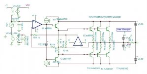
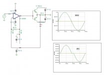
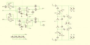
And what about this, still the same single op-amp as before, but now with floating supply.
Same NJW0281/NJW0302, same 1.4V Bias and same emitter resistors as you used but now even without the pre-drivers that you used.
I think this FDR topology is very simple but almost unbeatable, and remember, it can even be nested to gain at least another 50dB.
Hans
P.S. Op-Amp supply is now +/- 12V, but can be reduced to +/-5V without any negative consequences.
I also saw that the second emitter resistor is 200m instead of your 400m. When changing to 400m, distortion remains the same.
Attachments
Last edited:
First, you have biased the outputs 0.850A, running the test at class A. Using a more performant THS4631 with 80ma output current vs 30ma, I get maximum output 4Vp. You need absolutely a driver.
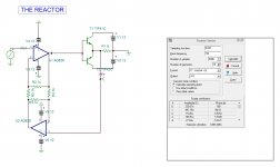
I am working on Hec for class d, as most are bridged, I am working on a differential Reactor. Mybe you can give me ideas.
Hayk.
I am working on Hec for class d, as most are bridged, I am working on a differential Reactor. Mybe you can give me ideas.
Hayk.
Last edited:
It works, 0.008%. with 150ma bias and 330pf . But what it will be with triple pairs?
Last edited:
Sorry you are wrong. I used the same bias as you did, giving ca 100mA bias.First, you have biased the outputs 0.850A, running the test at class A. Using a more performant THS4631 with 80ma output current vs 30ma, I get maximum output 4Vp.
For 0.8A, you will need 3.0V bias instead of 2.8V.
It was just an rough example to get an idea and yes for more power one will definitely need a predriver stage.
Hans
ONsemi provides both LTspice and Spice2/3, maybe yours is different . 0.7v seams too high for 100ma, but with mine the N needs 0.55v and the P 0.75v for 150ma, very strange isn't it.
I suspected something like that.
Since 99% of all sims on the DIYAudio forum are made with LTSpice, it might be a good idea for you to switch from Tina.
That makes exchanging info quite a bit easier.
Hans
Since 99% of all sims on the DIYAudio forum are made with LTSpice, it might be a good idea for you to switch from Tina.
That makes exchanging info quite a bit easier.
Hans
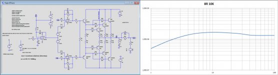
This is how it looks with an extra stage and a triple output transistors.
THD creeps slowly from 1ppm to 10ppm and then to 7ppm at 100Watt.
In combination with your idea for two additional closed loops with the AD8008 around the two output stages would easily result way below 1ppm.
Hans
THD creeps slowly from 1ppm to 10ppm and then to 7ppm at 100Watt.
In combination with your idea for two additional closed loops with the AD8008 around the two output stages would easily result way below 1ppm.
Hans
Attachments
I see I convinced you how simple and quality design can outcome from floating mode controller. Maybe what you call FDR.
Is the distortion graph from a plugin, I don't find on my LT version this option.
Is the distortion graph from a plugin, I don't find on my LT version this option.
Last edited:
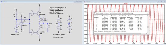
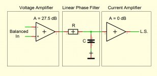
I may seem so, but I designed my amp 5 years ago with a 27.5dB differential voltage amplifier and a separate 0dB current amplifier, same idea as LKA used.
The latter has a nested FDR (Feedback Distortion Reduction) made with floating amps, see image below.
Measured THD at all voltages up to 28Veff, frequencies up to 10kHz and load up to 4R is around or below one digit ppm level.
Hans
The latter has a nested FDR (Feedback Distortion Reduction) made with floating amps, see image below.
Measured THD at all voltages up to 28Veff, frequencies up to 10kHz and load up to 4R is around or below one digit ppm level.
Hans
Attachments
Let the parametrized source voltage in LTSpice make a suffucient number of steps with the .step command and view in the error log for their resp. fourier distortion numbers.Is the distortion graph from a plugin, I don't find on my LT version this option.
Export these numbers to Excel and voila, there’s your graph.
Hans
- Home
- Amplifiers
- Solid State
- Simple high power BJT/MOSFET G=0.6db output with Hawksford error corrector .