I've really been liking the sound of this amp, more than the DCA or the AKSA HPA!
Glad it’s working out for you - there is something to be said for a DC-coupled design. It passes everything through clearly. The other amps are AC coupled single rail, single ended Class A designs, which will sound different due to the topology and the fact that they are capacitively coupled. The DCA is dead simple compared to this one though.
Just to follow up, I realised that I had missed the two 1uF film caps (C137 etc). It seems this was causing some instability and part of the sensitivity when I put my hands near the other film caps.
I installed those and disconnected the loop breaker to test and the noise dropped to a tolerable level, but still getting capacitive coupling with the chassis.
With the loop breaker in place, the amp is silent and happy.
I'll still try and hunt down where the grounds are getting mixed (engineer OCD) but regardless, this amp sounds great.
Thanks for all the work in bringing this to us, XRK et al.
Last edited:
Glad to hear that it’s working out. You have some sort of capacitive coupling between your board ground and the case it seems. Keep the GLB between the signal GND and case and maybe use larger 51R resistor even plus 100nF film cap in parallel.
Thanks X. I'll have a play around again when I get a chance. Too many projects to dwell too long! (Got all the bits for a Korg B1 that won't assemble itself!).
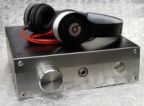
In the meantime, I'm pretty happy with the finish on this build.
In the meantime, I'm pretty happy with the finish on this build.
Attachments
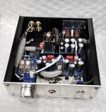

Avtech, I really like what you did with the wiring in your amp! I have been experimenting with mumetal shielding and ferrite beads lately, so definitely interested in preventing stray EMF pickup.
Let me see if I have your process figured out...So you twist up the wire pairs, then slip on that braided shielding sleeve along with two bits of heat shrink OVER the sleeve (that looks like it was hard). Solder wires. Then finish by slipping the heat shrink down to the ends, to cover the joints and secure the ends of the shielding sleeve in place. Man, that is cool.
Did I get it right? Where do you get that shielding material?
I think that’s just silver colored decorative nylon braid to tidy things up. To make shielding you would tie just one end to GND. Twisting pairs of wires does help reduce stray noise pickup.
Thanks Stellar,
For this particular build I just used the nylon braid, as X correctly identified, to tidy up the cables and make it a bit neater. The cables themselves were multicore sheilded already so I didn't need the extra shielding.
I've used similar products to this a fair bit at work and it seems to do the job: 30508 | Wurth Elektronik Expandable Fibreglass, Nickel Plated Copper Grey Cable Sleeve, 8mm Diameter, 1m Length | RS Components
For this build, I attached the JST connectors to the wires at both ends. Then using a plastic tube, compressed the sleeve to open it up, slip onto the tube then feed the wire through the tube. Heatshrink (unshrunk) on one end, withdraw the tube most of the way, laying the sleeve on the wire, then pop the second heatshrink on the sleeve. Hit it with a hot air gun and ready to go!
Avtech,
That woven fiberglass/copper braid looks like great stuff but pricey at $32/meter. I guess you don't need much of it for a small preamp or HPA box. Thanks for the link.
I wonder if solder wick braid could be used for smaller cables. Sometimes, stripping off braid from used RG58 coax or household cable coax leftover bits can work too.
Thanks X. I'll have a play around again when I get a chance. Too many projects to dwell too long! (Got all the bits for a Korg B1 that won't assemble itself!).
In the meantime, I'm pretty happy with the finish on this build.
this looks great, the sleeves are a nice touch - looks like you took a page out of the PC building book 😛
Thanks buzz.
True, it does look like the PSU leads inside my PC! Must've been where the inspiration came from 😉
I'll play around with it again at some point - I have an additional input to wire in when I decide what to put in - and might change the PVC out for the proper shielding sleeves (I've got an old stash of it somewhere).
I'm currently running an rPi with Volumio through an original hifiberry dac into some Audio-Technika ATH-M50x and it sounds pretty nice to me. Definitely worth the headache of soldering SMD!
I'v got my BF862s from one of recommended ebay links, but they all seem to have Idds around 30mA. That's wrong... at least according to the data sheet... isn't it? So I'm thinking about using MMBF5458 instead. I have 50 of them laying around, they should fit as well as 2sk209, at least with respect to 2mA current, correct?
Idss of 30mA seems high. But you know, it might work fine. How did you measure Idss?
2SK209 should work as well but may require revised resistor DC setpoints. Since you have the “questionable” BF862’s, try them. Easy to remove and install new ones if no good. I can’t imagine anyone bothering to make a fake 25 cent part. Are markings “2AW”? If not demand refund from seller. BF862 mark is 2AW.
2SK209 should work as well but may require revised resistor DC setpoints. Since you have the “questionable” BF862’s, try them. Easy to remove and install new ones if no good. I can’t imagine anyone bothering to make a fake 25 cent part. Are markings “2AW”? If not demand refund from seller. BF862 mark is 2AW.
I have invested in this guy together with DCA75: SOT23 Peak Component Adapter | Peak Electronic Design Limited. Measuring gig is grand, I have checked 2sk170 on it and it's fine, still shows same Idss as a year ago when I got it.
So I'm looking again at one of the BF862s right now and it stabilized @31.2mA.
Edit: markings are actually 2Ap and 48 written 90 degrees on the side.
Checked my ebay history: this is where I get them from: 50PCS BF862 ORIGINAL JFET N-CHAN 20V SOT-23 | eBay
So I'm looking again at one of the BF862s right now and it stabilized @31.2mA.
Edit: markings are actually 2Ap and 48 written 90 degrees on the side.
Checked my ebay history: this is where I get them from: 50PCS BF862 ORIGINAL JFET N-CHAN 20V SOT-23 | eBay
Last edited:
Hmm... 2Ap is also code for BF862.
BF862,SmdCode:2Ap,Package:SOT-23 - Marking Codes
Idss of NXP can be as high as 25mA. It is very possible you have some “hot” ones as there is a distribution. I used to save these hot ones for special cases where I wanted a higher Idss.
30mA is not unreasonable for something that has a range up to 25mA.
https://www.nxp.com/docs/en/data-sheet/BF862.pdf?
I would t worry about and just use them.
- Home
- Group Buys
- Simple High Performance DC Coupled Class A HPA with sub PPM THD