You still haven’t shown us the schematic with voltage written in for each leg of each transistor (not delta V across the resistors). All voltages relative to 0v. Especially the V131 BJT that drives the quiescent bias current setpoint. Have you checked to make sure it is correct and functioning as a PNP? Remove the V131 and check to make sure it’s not dead or swap with V111. In my experience the BF862’s hardly ever are bad - and the voltages you show seem to indicate they are operating balanced like the upper circuit. It doesn’t look like the MOSFETs are the problem since you checked and swapped. I would focus on V131 and resistors around it.
ahh my mistake! I was measuring similar points to what was shown on the LTSpice screengrab - which seemed to be across resistors. Will probe around tomorrow!
continuity measured on +/- rails to mosfets & R132 - all good there.
Resistance across R131 & R132 give 1.x Kohm though and it slowly increases as I keep the probes across each resistor. Compared to R111 & 112 which give 2.2k almost straightaway from applying probes.. Not sure what that means though
Resistance across R131 & R132 give 1.x Kohm though and it slowly increases as I keep the probes across each resistor. Compared to R111 & 112 which give 2.2k almost straightaway from applying probes.. Not sure what that means though
You don't have your negative rail voltage on the Drain of V134.
If you are using the power supply board, check that the power connector X241 has V+ on pin 3, V- on pin 1 and GND pin 2.
Did you check the polarity of V241 per the correction (silkscreen was wrong)?
If you are using the power supply board, check that the power connector X241 has V+ on pin 3, V- on pin 1 and GND pin 2.
Did you check the polarity of V241 per the correction (silkscreen was wrong)?
avtech23:
V+ V- and GND are all coming through correctly - PSU outputs are normal, and JST connector to board is fine too (measured voltages at those pins)
except....traces have continuity with the leg of the mosfet...You don't have your negative rail voltage on the Drain of V134.
V+ V- and GND are all coming through correctly - PSU outputs are normal, and JST connector to board is fine too (measured voltages at those pins)
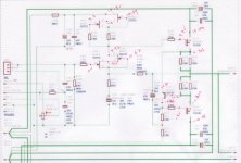
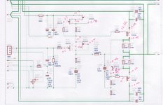
Your upper amp has -16v on the negative rail as shown by drain pin of MOSFET on left diagram. The amp that is not working (right diagram) shows 0v at the drain of the bottom MOSFET. You may have just not pushed the probe hard enough to get a proper voltage since the top amp and bottom amp share the same rails. But it must show -15 or -16v. See marjed up diagram.
Attachments

X - quite correct. Took the measurement off the leg this time and -16V . Probably didn't contact the pad earlier.
I was puzzling over that earlier - how there could be -16 on one channel but not the other with traces intact. At least that mystery is solved!
What voltage is at R132 both sides wrt ground?
What voltage is at R132 both sides wrt ground?
Ok - rather inexplicably it works now. after checking for -16V I decided to swap out the BC857 as X suggested earlier. Put it on the transistor tester - it checked out. New one from the pack, also tested fine. Put in the new one and now voltages seem to be similar to the L channel (no sound test yet).
No idea why that did the trick - I did check the BJT for shorts before pulling it and it didn't seem like there were any.
No idea why that did the trick - I did check the BJT for shorts before pulling it and it didn't seem like there were any.
I bet it was a cold solder joint on the BC857. Let us know what you think of the sound. For me, it’s one of the best headphone amps I have heard. Being DC coupled really gives it some amazing transparency and the depth of bass is very good.
I actually killed my 7918 shortly after..I think the pins worked loose while testing and there was a spark.
Listening will have to wait until I get around to modifying the ldovr reg..
Listening will have to wait until I get around to modifying the ldovr reg..
Got the amp running with the ldovr regs (swapped the resistor as alexy said) and adjusted to within <0.1V on +ve and -ve rails.
My hardest to drive pair of headphones are Fostex T50rps. With a fraction of a turn of the volume knob its up to slightly higher than normal listening volume, and just for fun I turned it up higher (headphones on the desk of course). You weren't kidding when you said this thing has power!
Will have to get it mounted up for a more extensive listening session & comparison.
I'm kind of itching to build another to use as a speaker amp as you suggested
YOB,
Glad to hear that the sound is good so far. Please post detailed descriptions of which resistor you modified on the LDOVR to program the correct voltage.
Glad to hear that the sound is good so far. Please post detailed descriptions of which resistor you modified on the LDOVR to program the correct voltage.
replace R7 (1M5 resistor @ top right corner - 0.3V pad) with 105K (SMD 0603)
after modification 0.3V PAD will add 4V - you can configure from 3V to 22V with 1V step
for 20V - need to solder 8V, 4V, 1V and 0.3V (now 4V) pads
Vout = 3+8+4+1+4 =20V
Here. The modification is only required for the negative reg.
X - perhaps link this in the first post?
Been listening and comparing this amp to a few others - mainly with Fostex T50rp mk3.
This amp is great, drives them well and brings out low lingering bass on the T50s.
Vs DCA - DCA doesn't give as much bass response
Vs Aksa Lender HPA - to my ears sounds quite similar
Vs O2 - O2 is positively anemic with the Fostex, and distorts as well. DCA much more worth it for the price O2s go for!
YOB,
Thanks for the listening impressions. I have heard similar comments about the O2 vs even the little Pocket Class A. The DCA has 125mA, more than double the bias current. This amp, is in another class because it has an active CCS that sort of makes it a push pull even though it is SE Class A. The DC coupling makes a difference too. The PSU in this amp is truly state of the art - you can’t get a quieter power supply that is wall powered.
Thanks for the listening impressions. I have heard similar comments about the O2 vs even the little Pocket Class A. The DCA has 125mA, more than double the bias current. This amp, is in another class because it has an active CCS that sort of makes it a push pull even though it is SE Class A. The DC coupling makes a difference too. The PSU in this amp is truly state of the art - you can’t get a quieter power supply that is wall powered.
- Home
- Group Buys
- Simple High Performance DC Coupled Class A HPA with sub PPM THD