RFI filtering and protection of the input FETs, as well as bandwidth limiting so that it does not oscillate. You can short out the 100R and it may work fine, but you may have RFI problems and it may oscillate...
I understand the filtering part.
I am thinking that a 2K2 resistor at the gate would be enough or perhaps I’m missing something.....
I am thinking that a 2K2 resistor at the gate would be enough or perhaps I’m missing something.....
Perhaps I didn't explain it clearly in my previous post.
I am proposing to move the 2K2 resistor to the gate, as a gate stopper. In front of it, the two capacitors will act as high pass and low pass filters.
Is there an issue doing this with a FET input?
I am proposing to move the 2K2 resistor to the gate, as a gate stopper. In front of it, the two capacitors will act as high pass and low pass filters.
Is there an issue doing this with a FET input?
Harry3,
Can you mark up the schematic with what you are proposing?
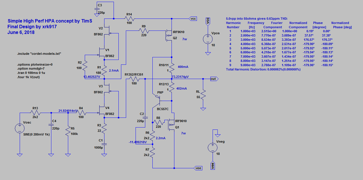
Do you mean make R13 2k2 and get rid of the 100R? The 2k2 acts with C4 as a filter, whereas the 100R is a gate stopper, which probably isn't needed as the 2k2 is already there. However, it matters where the node to the filter cap is located. I think you can leave R13 where it is but ok to get rid of the 100R at R4.
Can you mark up the schematic with what you are proposing?
Do you mean make R13 2k2 and get rid of the 100R? The 2k2 acts with C4 as a filter, whereas the 100R is a gate stopper, which probably isn't needed as the 2k2 is already there. However, it matters where the node to the filter cap is located. I think you can leave R13 where it is but ok to get rid of the 100R at R4.
Last edited:
OK. I now see what you are saying about where the node should be.
I will leave the 2K2 resistor in it's original position.
I will leave the 2K2 resistor in it's original position.
Hi XRKaudio , I was wondering the status of my order - I received your invoice on Oct.2nd and 63.00 was sent on Oct.3rd by PAYPAL for -- a Simple DC Coupled Class-A HPA PCB Panels , Qty -2 . Hope all is well and postal company hasn't lost it somewhere.
Hallcon,
Oh so sorry about that! That’s a long time. Let me check to see what’s going on. Should not have taken more than 1 week, so it’s either I totally messed up and forgot to send it or it is lost.
X
Oh so sorry about that! That’s a long time. Let me check to see what’s going on. Should not have taken more than 1 week, so it’s either I totally messed up and forgot to send it or it is lost.
X
Hi Hallcon,
I just checked and it looks like I totally messed up and just forgot to send your order. Let me help make this up to you... I will throw in a free Desktop SE Class A (DCA) amp PCB for your troubles. I will send it out tomorrow via priority mail.
Cheers,
X
I just checked and it looks like I totally messed up and just forgot to send your order. Let me help make this up to you... I will throw in a free Desktop SE Class A (DCA) amp PCB for your troubles. I will send it out tomorrow via priority mail.
Cheers,
X
Only just getting around to building this now!
With the ldovr regs is it just bridging pads so they total up to the desired output voltage?
With the ldovr regs is it just bridging pads so they total up to the desired output voltage?
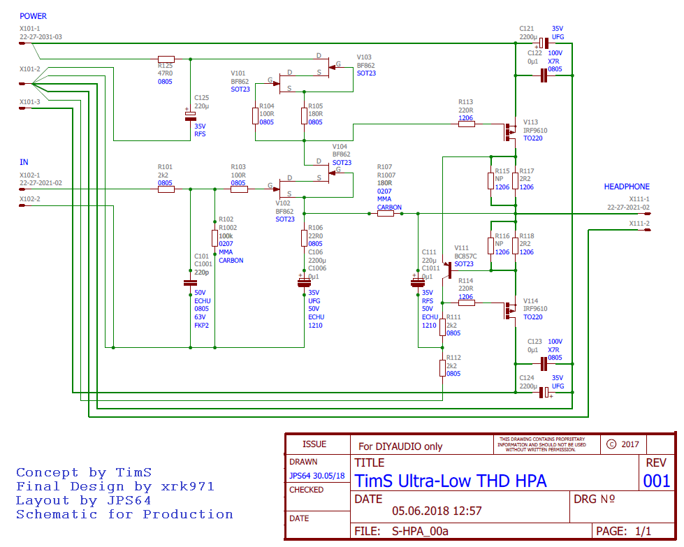
2. For the main MOSFET Drain resistors R117/118 and R137/138, please use high quality metal thin film as well. I only had thick film on hand, so once again, you may see significant improvement in distortion over my verification build if you choose this. I would start with the 2R7 values to get 115mA. If you really want 145mA then use 2R2 and that will be the maximum capability of the Traco Dc-DC (315mA for both channels).
X - found an inconsistency.
Thin or thick film for these ones (R117/118 and R137/138)? BOM lists thick for these (and that's what I ended up ordering), but you advise thin in the quoted post.
Thanks
Also, in the schematic some resistors are specified as carbon, but bom doesn't mention any carbon resistors all.
IMO - thin film resistors are generally the best you can get. They are stable, tight tolerance, low PPM, non magnetic and are made of good quality raw material etc etc...
Some people like carbon resistors because they have their own "signature" sound.
You choose your poison😀
Some people like carbon resistors because they have their own "signature" sound.
You choose your poison😀
On the feedback resistors (R16/107) and MOSFET source/drain power resistors (R115/116/117/118) especially, use either carbon film or metal thin film. If you use metal oxide thick film here, it tends to generate the unpleasant third order harmonic distortion. I have measured it and it is not insignificant. But only in places where there is a significant amount of AC-signal current induced heating. Some people argue that gate stoppers (R113/114) for MOSFETs should be carbon as well.
To be safe, use all metal thin film if you want. It will cost a bit more but will be safe and low distortion. The carbon thin film on the key feedback and ground shunt resistors will have a smoother ("less etchy metallic") sound.
To be safe, use all metal thin film if you want. It will cost a bit more but will be safe and low distortion. The carbon thin film on the key feedback and ground shunt resistors will have a smoother ("less etchy metallic") sound.
Last edited:
ahh gotcha - thanks X thanks Harry3!
Guess I'll be ordering some thin film / MELF 2R7 & 180R carbon resistors to muck about with.
2R7 backordered @ RS until March, so I guess I'll have it running on the thick film until then, carbon TH available for next business day delivery 😀
Guess I'll be ordering some thin film / MELF 2R7 & 180R carbon resistors to muck about with.
2R7 backordered @ RS until March, so I guess I'll have it running on the thick film until then, carbon TH available for next business day delivery 😀
It’s a minor effect so go ahead and run on thick film. Your ears may not even know the difference.
- Home
- Group Buys
- Simple High Performance DC Coupled Class A HPA with sub PPM THD