In the DDDAC thread, we keep on discussing the best options for power supplies. The DDDAC itself needs a clean 8 VDC, and the various "helper" boards need 5 V or 3.3 V (USB/I2S converters, I2S reclockers, etc.). The general gist seems to be that its easy to make PSUs for these voltages using the typical regulators (78xx, LFxx, LDOs), but other options without any regulator feedback loops seem to allow better sonic results.
People keep bringing up battery supplies. Batteries are certainly great fixed-voltage supplies for their low noise and absence of mains hum, and there is not regulator feedback loop. However, batteries need charging from time to time, so they are inconvenient in situations where the electronics are always turned on.
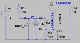
I had a (crazy?) idea for a mains-powered power supply, but using batteries... consider a good old fixed-voltage power supply using a Zener voltage reference and a transistor (Darlingon or Sziklai if you want) as a buffer for the Zener voltage (see attachment). This circuit provides a well-defined fixed output voltage without any sensing of the output voltage to regulate the output, i.e., there is no feedback loop.
Now, Zeners are known to be rather noisy. There are ways to deal with the noise -- but what if the Zener would be replaced with a battery, much like with battery bias in a tube amp? The battery also provides a fixed voltage, but it does not add noise. And it's a battery, and people seem to like batteries.
Would that work? Would it work well? Comments, thoughts?
People keep bringing up battery supplies. Batteries are certainly great fixed-voltage supplies for their low noise and absence of mains hum, and there is not regulator feedback loop. However, batteries need charging from time to time, so they are inconvenient in situations where the electronics are always turned on.
I had a (crazy?) idea for a mains-powered power supply, but using batteries... consider a good old fixed-voltage power supply using a Zener voltage reference and a transistor (Darlingon or Sziklai if you want) as a buffer for the Zener voltage (see attachment). This circuit provides a well-defined fixed output voltage without any sensing of the output voltage to regulate the output, i.e., there is no feedback loop.
Now, Zeners are known to be rather noisy. There are ways to deal with the noise -- but what if the Zener would be replaced with a battery, much like with battery bias in a tube amp? The battery also provides a fixed voltage, but it does not add noise. And it's a battery, and people seem to like batteries.
Would that work? Would it work well? Comments, thoughts?
Attachments
It will work as such but I anyway have some comments:
Batteries have no hum but many say that they are not at all noiseless.
Batteries have a rather limited lifetime so the construction will not work for a decade without battery replacement.
For a rather constant battery and output voltage, you will need to use a rechargeable battery. Then, you need to include a battery charger circuit. Only a current limiting resistor will make the battery life shorter.
The DDDAC may have a varying current consumption that makes the voltage on the output of an ordinary voltage regulator swing and that is why a non-regulated circuit seems to perform better.
If you want the lowest noise and the fastest response to changes in the current consumption, use a shunt regulator. For minimum hum, buy a transformer with primary and secondary shields. They are probably found for medical use. My advise. I suspect that you will soon be disappointed with your battery hybrid though your idea is logical and will work as such .
NB: With a battery you will have problems getting the exact voltage you want.
Last edited:
Certainly not a new idea: Weston cell - Wikipedia
It can be made to work, and even with the nineteenth century technology, it was possible to use this voltage (almost) without drawing any current.
It is possible to replicate it with modern means, but first you need to question the actual superiority of such a scheme, and the way you are going to buffer it: any normal type of buffer/follower has 100% feedback, which seems undesirable from your POV.
There are methods of cancellation using positive feedback instead, but you probably consider them as an even greater evil.
Anyway, technology-wise, it is perfectly doable: a lithium battery lives ~for ever if no current is drawn, and even a humble alkaline cell will provide its 1.59V for a very long time, provided it has a decent quality (good purity of ingredients), is not depleted or subjected to temperature variations.
That said, any circuit that uses a zero-drain battery could equally well use a passively-filtered reference like a bandgap or a zener....
Perhaps something like this would work...but 100nf capacitor paralleled to a zenner will kill most of the noise which makes this circuit silly. You only need to use a discharged battery at first so that you won't kill a lower power zenner diode .") 8v2 zenner wouldn't be good to use with a 9v battery because the battery will steal all the current from the transistor base trying to charge . The resistor value need to be adjusted with the real battery , just made a quick drawing...
8v2 zenner wouldn't be good to use with a 9v battery because the battery will steal all the current from the transistor base trying to charge . The resistor value need to be adjusted with the real battery , just made a quick drawing...
8v2 zenner wouldn't be good to use with a 9v battery because the battery will steal all the current from the transistor base trying to charge . The resistor value need to be adjusted with the real battery , just made a quick drawing...Attachments
Last edited:
Whats the purpose of the Zener? Wouldn't the battery set the voltage on it's own? The voltage will of course depend on the battery type.Perhaps something like this would work...but 100nf capacitor paralleled to a zenner will kill most of the noise which makes this circuit silly. You only need to use a discharged battery at first so that you won't kill a lower power zenner diode .
I would have thought a CR2032 lithium button cell would be quite a good reference, shelf life is 10 years, and you can readily get pcb mounting and panel mounting holders for them.
Note that the internal impedance is quite large for small cells, so don't draw much current.
But then again one capacitor and one zener isn't so bad, and a precision low noise voltage reference carefully buffered is excetionally good.
Many years ago special batteries were used as calibration voltage sources, for instance the Weston Standard Cell - they were chosen for repeatable chemistry with low temperature coefficient. Random modern batteries don't necessarily have a low tempco though.
The requirment was for an 8v regulated source. The battery is rechargeable...and the 9v1 zenner doesn't allow it to fully charge so the battery's lifespan will be protected...of course a 10v precision reference is welcome...Whats the purpose of the Zener? Wouldn't the battery set the voltage on it's own? The voltage will of course depend on the battery type.
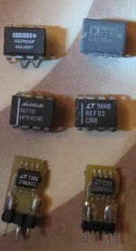
https://datasheets.maximintegrated.com/en/ds/REF01-REF02.pdf
http://www.ti.com/lit/ds/symlink/ref102.pdf
https://www.analog.com/media/en/technical-documentation/data-sheets/lt1236.pdf
https://www.analog.com/media/en/technical-documentation/data-sheets/1021fc.pdf
Attachments
In the DDDAC thread, we keep on discussing the best options for power supplies. The DDDAC itself needs a clean 8 VDC, and the various "helper" boards need 5 V or 3.3 V (USB/I2S converters, I2S reclockers, etc.). The general gist seems to be that its easy to make PSUs for these voltages using the typical regulators (78xx, LFxx, LDOs), but other options without any regulator feedback loops seem to allow better sonic results.
People keep bringing up battery supplies. Batteries are certainly great fixed-voltage supplies for their low noise and absence of mains hum, and there is not regulator feedback loop. However, batteries need charging from time to time, so they are inconvenient in situations where the electronics are always turned on.
I had a (crazy?) idea for a mains-powered power supply, but using batteries... consider a good old fixed-voltage power supply using a Zener voltage reference and a transistor (Darlingon or Sziklai if you want) as a buffer for the Zener voltage (see attachment). This circuit provides a well-defined fixed output voltage without any sensing of the output voltage to regulate the output, i.e., there is no feedback loop.
Now, Zeners are known to be rather noisy. There are ways to deal with the noise -- but what if the Zener would be replaced with a battery, much like with battery bias in a tube amp? The battery also provides a fixed voltage, but it does not add noise. And it's a battery, and people seem to like batteries.
Would that work? Would it work well? Comments, thoughts?
But basically what you have is an emitter follower, 'following' the zener voltage. Emitter follower have lowish output impedance, but not very low. So the varying load current that the DAC draws will cause ripple at the emitter output, and thus on the supply rail.
From a well regulated power supply point of view, it is not very good. Replacing the zener with a battery does not negate the weak point of the emitter follower. Any improvement has to come from a regulation loop.
Jan
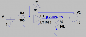
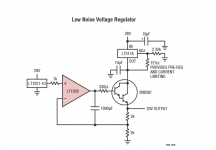
add an op-amp with a gain of 3x to a 3v battery...R2 can be part of the equation if added to the internal resistance of the cell and readjusted R1.The internal impedance looks like in between 110ohms and 50 ohms...and that can be substracted from the input resistor R2 .Usually you have a precision voltage referencing a high impedance input unity buffer cause you don't want that battery to last 1 hourI would have thought a CR2032 lithium button cell would be quite a good reference, shelf life is 10 years, and you can readily get pcb mounting and panel mounting holders for them.
Note that the internal impedance is quite large for small cells, so don't draw much current.
This axample should be included in the Bad examples section of the fifth Art of electronics edition ! Better take the LT1028 datasheet for reference https://www.analog.com/media/en/technical-documentation/data-sheets/1028fd.pdf
Attachments
Last edited:
- Status
- This old topic is closed. If you want to reopen this topic, contact a moderator using the "Report Post" button.
- Home
- Amplifiers
- Power Supplies
- Simple fixed voltage PSU with a battery as voltage reference?