For a LM3886 chipamp project.
Drops +/-35V from the main regulated power supply (sill in development, nearly there) down to +/-15V and +/-12V. Two of these in series will be used rather than using symmetric regulators (easier to construct this way, for one thing).
15V used by FET buffer.
12V isn't necessary at the moment but maybe used for a relay based source selection switch (if I can be bothered). Prefer to alter the switch circuit to work with +/-15V rather than use this extra regulator but I'm still massaging overall design details.
Any comments, suggestions or corrections welcome.
Attachments

Hi,
r1, 2 & 3 are shown as 1W, why?
Have you calculated the currents and the powers through these resistors?
why have you shown 1k2 & 100r, when 1k3 can do the job?
U1 has 20V across it.
U2 has 3V across it.
What does the datasheet sheet say about this?
What is the range of input voltage?
What is the range of ripple voltage on that unregulated DC supply?
Last edited:
I too wonder why you're meaning to use 1W resistors, since the current running through R1...R3 is low enough to use 0.25 W resistors.
What I also wonder about is why you chose 120R for R1 when 240R would be fine to get stable operation. With R1=240 and R2=2k6 you will meet the minimum load current requirement of 3.5-5 mA (even without load) while cutting the power dissipated in R1...R3 in half.
What is the current you're going to draw from the 15V (including what the 12V circuit would draw if used)? With a drop of 20 V across the LM317T you would need heatsink above 100 mA current at an ambient temp of 25C.
I have no problems with the 12V setup, Vin-Vout is sufficient (usually needs to be at least 2-2.5V), but I would add 100nF capacitors between Vin-gnd and Vout-gnd as close to the pins as possible to supress any noise from the LM7812.
Hi,
r1, 2 & 3 are shown as 1W, why?
Have you calculated the currents and the powers through these resistors?
why have you shown 1k2 & 100r, when 1k3 can do the job?
U1 has 20V across it.
U2 has 3V across it.
What does the datasheet sheet say about this?
What is the range of input voltage?
What is the range of ripple voltage on that unregulated DC supply?
I checked U1 and U2. U2's minimum voltage is 2V so it's close but U1 can have up to 40V differential.
The resistor power ratings: was blindly guessing because I don't know what the power requirements of the buffer are (circuit here STEREO FET BUFFER FOR DAC, PREAMPLIFIER, TAPE REC, ... (eBay item 380167086814 end time 06-Nov-10 03:41:04 AEDST) : Computers Networking). Will look at the maximums of the semiconductors to get an idea - any more accurate assessment is beyond my ability.
Thanks
I too wonder why you're meaning to use 1W resistors, since the current running through R1...R3 is low enough to use 0.25 W resistors.
What I also wonder about is why you chose 120R for R1 when 240R would be fine to get stable operation. With R1=240 and R2=2k6 you will meet the minimum load current requirement of 3.5-5 mA (even without load) while cutting the power dissipated in R1...R3 in half.
What is the current you're going to draw from the 15V (including what the 12V circuit would draw if used)? With a drop of 20 V across the LM317T you would need heatsink above 100 mA current at an ambient temp of 25C.
I have no problems with the 12V setup, Vin-Vout is sufficient (usually needs to be at least 2-2.5V), but I would add 100nF capacitors between Vin-gnd and Vout-gnd as close to the pins as possible to supress any noise from the LM7812.
See reply above too.
Two resistors were used in series because none of the local electronic retailers stock the correct value at 1W. The problem goes away with smaller rated resistors.
I was reading up on good 317 design and 120R was recommended for better regulation. It was a while ago and I neither recall where I saw it or what reason was given. I'll try to find it. In any case, I'm more than happy to go 240R (as per datasheet, I notice) and use 1/4W resistors.
Thanks for your help...
the 120r or 240r option for the upper voltage setting resistor is chosen to guarantee a minimum output current for the regulator if the client circuit draws near zero current during part of it's normal operations.
The "real" lm317 has a minimum draw of 5mA.
The "real" lm337 has a minimum draw of 10mA.
I have no idea what the undocumented copies and fakes have as a minimum current draw.
It seems wise, to me, to always adopt a guaranteed minimum draw of >=10mA for all undocumented 3pin regs. That demands <=120r for the 1.25V that is the output of the 3pin regulator.
Now that the resistor has been chosen one can determine the current flowing to ground through the voltage setting resistor string. Use I^2 * R to find operating power.
where did you buy your 2k6 resistors?..........With R1=240 and R2=2k6 ......
🙂 When going shopping for parts today, I assumed it was a typo. 2k7 gets 15.3V while 2k6 gets 14.7V.where did you buy your 2k6 resistors?
---
Revision.
- Resistors changed.
- Read a little about tantalum capacitor reliability issues (like an often closed-circuit mode of failure), so dropped those for low-ESR electrolytics. Larger value than before but I have them so may as well use them as their value isn't critical.
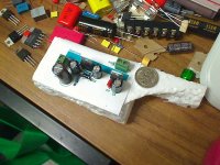
Will probably move the connection pins to have 5mm spacing so screw terminal blocks can be used.
Tested component PCB footprint with polystyrene foam (pictured). Looks fine apart from over-sizing the outer diameter of the 470uF capacitor by a few mm.
Attachments

Hi,
low ESR caps across the output of 3pin regs may not be suitable.
See what the datasheets say about caps at input and output.
low ESR caps across the output of 3pin regs may not be suitable.
See what the datasheets say about caps at input and output.
from that link
the graph shows what should be checked for and avoided.Output impedance versus C2's ESR: 10mR (red), 100mR (green), 1000mR (blue). C2 = 220 uF
How bad exactly is shown above. The hypothetical 220uF/10mOhms capacitor gives rise to a massive resonant peak at 5kHz.
where did you buy your 2k6 resistors?
Hi,
low ESR caps across the output of 3pin regs may not be suitable.
See what the datasheets say about caps at input and output.
the graph shows what should be checked for and avoided.
Wow, that article is really interesting. Thanks so much. Back to drawing board.
I checked U1 and U2. U2's minimum voltage is 2V so it's close but U1 can have up to 40V differential.
Yes, but rated max. power is only guaranteed to a Vi-Vo of max. 15 V. It's as low as 0.15 - 0.4 A when Vi-Vo = 40 V (but I presume that's without heatsink).
The resistor power ratings: was blindly guessing because I don't know what the power requirements of the buffer are
The requirements of the load are irrelevant for R1 and R2 (since this load is connected parallel to R1+R2). The only things relevant are Vout and the total value of R1+R2. This determines the current through (and thus the power dissipation of) R1 and R2.
🙂 When going shopping for parts today, I assumed it was a typo. 2k7 gets 15.3V while 2k6 gets 14.7V.
-
Oh, that was no typo. I was lazy and simply multiplied your 1k3 by 2 to get 2k6. The closest "real" value you can get is 2k61 (E48-range and up).
I always like to calculate the value with the full equation [Vout = Vref x ( 1 + R2 / R1) + ( Iadj x R2)] and not the simplified one (without Iadj x R2).
With the full equation and typical values for Vref and Iadj, you'll see that the output is nearly at 14.9 V, and not 14.7 V (R1=240R, R2=2k61).
In most aplications that need 15 V, this value isn't that critical and anything from 14.5 - 15.5 V will do. But if more precision is required, you'll find that deviation of Vref and Iadj (esp. the former) from the typical value will have a siginificant effect on the output. Just a 0.02 V higher Vref with the abovementioned resistors will result in nearly 0.25 V higher Vout.
the 120r or 240r option for the upper voltage setting resistor is chosen to guarantee a minimum output current for the regulator if the client circuit draws near zero current during part of it's normal operations.
The "real" lm317 has a minimum draw of 5mA.
The "real" lm337 has a minimum draw of 10mA.
I have no idea what the undocumented copies and fakes have as a minimum current draw.
It seems wise, to me, to always adopt a guaranteed minimum draw of >=10mA for all undocumented 3pin regs. That demands <=120r for the 1.25V that is the output of the 3pin regulator.
Now that the resistor has been chosen one can determine the current flowing to ground through the voltage setting resistor string. Use I^2 * R to find operating power.
I'm spoiled with working in industrial electronics, only reputable brands there (guess where surplus goes 😉 ).
When I build a symmetric PSU, I use the same resistors for both LM317 and LM337 but connect the LED to indicate "power on" to the negative side.
Going back to original resistor control values where R1 = 120R and R2 = (two resistors) 1k2 and 100R), the most power dissipated is a very little over 0.1W for the 1k2.<snip>
Now that the resistor has been chosen one can determine the current flowing to ground through the voltage setting resistor string. Use I^2 * R to find operating power.
Aye. Thanks for pointing that out. Looking at the current vs differential V graph, it's going to be about 0.8A at maximum assuming a very big heatsink. Very hot indeed, possibly, considering the heatsink planned is quite modest. Hmmm.Yes, but rated max. power is only guaranteed to a Vi-Vo of max. 15 V. It's as low as 0.15 - 0.4 A when Vi-Vo = 40 V (but I presume that's without heatsink).
I could either 1) try it and see as at the moment I've little idea of potential current draw, 2) use a pass transistor to take, potentially, the majority of current load off the regulator or 3) use a different approach like a zener diode regulator or a zener diode coupled with a fixed 15V regulator.
I expect (well, ok, hope) there's a significant margin of error in the buffer's input voltage. Alternatively I could put a trimpot in for R1 and adjust to be pretty accurately 15V by hand.<snip>
In most aplications that need 15 V, this value isn't that critical and anything from 14.5 - 15.5 V will do. But if more precision is required, you'll find that deviation of Vref and Iadj (esp. the former) from the typical value will have a siginificant effect on the output. Just a 0.02 V higher Vref with the abovementioned resistors will result in nearly 0.25 V higher Vout.
.
Thanks for all help and guidance received.
Last edited:
Perhaps a better method than a 317 is to drop the voltage with a zener regulator (eg Pre-Regulator) then use fixed LM regulators.
Perhaps a better method than a 317 is to drop the voltage with a zener regulator (eg Pre-Regulator) then use fixed LM regulators.
Yeah, but the LM317 is pretty foolproof when you get the basics right. The mentioned variations in Vref and Iadj are between components, not within one.
Apart from very good regulation you also get overload and overheat protection, and those you don't get in the zener-reg.
What you need to find out is the current your FET buffer is going to draw (with and without the 12 V circuit).
Chances are something like that (but I don't know the design) draws very little and the Vi-Vo of 20 V is no problem whatsoever, maybe even without heatsink if the 12 V circuit is not installed.
Alternatively, you could do what one of our customers does (which I don't regard as elegant design, but it works perfectly) to drop more than 40 V: use two LM317s. The first to drop the voltage to, e.g. 24 V, the second to 15 V.
Last edited:
Hang elegance! 🙂Yeah, but the LM317 is pretty foolproof when you get the basics right. The mentioned variations in Vref and Iadj are between components, not within one.
Apart from very good regulation you also get overload and overheat protection, and those you don't get in the zener-reg.
What you need to find out is the current your FET buffer is going to draw (with and without the 12 V circuit).
Chances are something like that (but I don't know the design) draws very little and the Vi-Vo of 20 V is no problem whatsoever, maybe even without heatsink if the 12 V circuit is not installed.
Alternatively, you could do what one of our customers does (which I don't regard as elegant design, but it works perfectly) to drop more than 40 V: use two LM317s. The first to drop the voltage to, e.g. 24 V, the second to 15 V.
 Will this do?
EDIT: Should use 35V or higher rated capacitors in the 24V area. Corrected.
Thanks for your help...
Attachments
Last edited:
Hang elegance! 🙂
EDIT: Should use 35V or higher rated capacitors in the 24V area. Corrected.
Thanks for your help...
With the exception of R6, R7 and the 12 V circuit, that's more or less the same design. But if the current drawn is modest, save yourself money and space and go for the single LM317 option instead.
The LM317 (and '337) can take some abuse. I built a discrete class A headphone amp powered by LM317/LM337 set to +/- 25 V. I built this into a very small housing (stacking pcb's and tipping the toroidal to make everything fit), I still had to cut off half of the heatsinks on the regs. The housing has no ventilation slots and gets pretty warm to the touch, esp. in hot weather. This might result in the same kind of heating of the reg(s) as with a high Vi-Vo and modest power drain. I didn't even bother to put the protection diodes in. Despite all this the amp has been working perfectly over the last 10 years or so...
Last edited:
Hi Random,
the 1r0 output resistors ruin the 15V regulation.
The grounding as shown will send dirty signals into the ground sense pin of each reg, ruining their ability to give a clean output.
the 1r0 output resistors ruin the 15V regulation.
The grounding as shown will send dirty signals into the ground sense pin of each reg, ruining their ability to give a clean output.
- Status
- Not open for further replies.
- Home
- Amplifiers
- Power Supplies
- Simple DIY buffer PSU