Hi, I am looking to rebuild a small DC power supply for a valve heater. The specification is 3.25A 10V.
I have some old diodes that probably get a bit hot, but are still working.
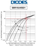
To understand the power (as heat) generated in the diode is it as simple as Vf in volts (at 3.25A from spec sheet showing Vf vs current) x 3.25 = Power lost (as heat) in Watts.
I will run the 4 diodes as a full wave bridge.
Does this make sense?
Rich
I have some old diodes that probably get a bit hot, but are still working.
To understand the power (as heat) generated in the diode is it as simple as Vf in volts (at 3.25A from spec sheet showing Vf vs current) x 3.25 = Power lost (as heat) in Watts.
I will run the 4 diodes as a full wave bridge.
Does this make sense?
Rich
1. Think of the 4-diode bridge as two diode-pairs. During the first half of the 50Hz mains sinewave, pair-1 conducts and pair-2 is off. During the other half of the mains sinewave, pair-1 is off and pair-2 conducts.
2. This means that pair-1 contributes 50% of the total output current and pair-2 contributes 50% of the total output current -- when taking the looooong term average over hundreds of cycles of mains sinewaves.
3. Diodes only conduct for a brief portion of the half-sine, as they refill the downstream filter capacitors. Emptying and refilling the filter capacitors is what causes "ripple" on the rectified and filtered output. Usually designers prefer quite small ripple, which means the diodes conduct for a VERY brief portion of the half-sine. In this case the diodes have to pass a total charge deltaQ (deltaQ = Cfilter * Vripple) in a small time deltaT, so the instantaneous current Idiode = deltaQ/deltaT is extremely high. Much much higher than (3.25 amperes / 2 diodepairs). Therefore the instantaneous power dissipation in the diode is very large.
4. Perhaps the easiest way to estimate the looooong term average power dissipation in each diode, is circuit simulation. It includes all of the intricacies of diode peak current, diode Vfwd versus current, and ripple voltage vs filter capacitor ESR.
Well I have no idea about the ones I am going to replace, and am trying to understand the specifications I am looking for in selecting the diodes.
I need a low Vf to make the circuit work, I tried some inappropriate Diodes I had and they got hot and the final voltage on the bench with an 'equivalent' supply was too low.
AC is 10.79V, DC out is 9.95V the circuit is CRC after full wave rectification with 47000uF R82 47000uF
Rich
I need a low Vf to make the circuit work, I tried some inappropriate Diodes I had and they got hot and the final voltage on the bench with an 'equivalent' supply was too low.
AC is 10.79V, DC out is 9.95V the circuit is CRC after full wave rectification with 47000uF R82 47000uF
Rich
Do you have a schematic for the original supply?
Which tube is this for?
All axial diodes will probably run kind of hot in your circuit.
Which tube is this for?
All axial diodes will probably run kind of hot in your circuit.
Upper bound:
The average current through each diode is known (usually half the DC current drawn from the supply, see Mark's post) and is by definition the time average of the momentary current through each diode.
The average power dissipation of each diode is by definition the time average of its momentary power dissipation, which is the time average of the product of its momentary current and momentary voltage. Assuming negligible reverse current, this is smaller than or equal to the time average of the product of the momentary current and the peak forward voltage, which equals the product of the average current and the peak forward voltage.
That is, if you can estimate the peak forward voltage and multiply that with the average current, you have a bit too high estimate for the diode dissipation.
Regarding estimating the peak forward voltage, if you know the peak forward current, you can usually look it up in the diode datasheet. The peak forward current, I mean the repetitive peak forward current, will definitely be less than the peak unloaded voltage of the transformer divided by its resistance (secondary resistance plus transformed primary resistance). As the diode forward voltage does not increase very quickly with current, this may be a good enough approximation.
You can derive a better approximation by assuming that the rectified voltage stays constant during the whole period, that the diode conducts whenever its input voltage exceeds its output voltage by 0.7 V or whatever and that the transformer has a certain internal resistance. You then end up with some goniometric equations and have to iterate the assumed rectified voltage until you get the right average current.
I'd go for any of (these) Schottky diodes in thru-hole, axial packages. All of them are rated for ten amperes (or more) of continuous current, all of them are rated for 45 volts or more of reverse voltage. In a 4-diode bridge circuit, the maximum reverse voltage any diode sees, is (Vout + 2Vfwd) which is eleven volts. 45 volt rated diodes have plenty of safety margin. They cost less than £0.57 per diode, qty=1.
_
_
Attachments
- Home
- Amplifiers
- Power Supplies
- Simple Diode question