Hi everyone,
I've been more interested in class B and AB projects, but now I'm also interested in class D because it has a much higher efficiency and good THD characteristics, and I wanted to learn more about this exciting technology. I've read some app notes from IR, the Bob Cordell chapters about class D and I've the IRAUDAMP1 app note.
But unlike class AB and B, I can't find details about the implementations, almost all of the schematics are block diagrams and I don't know how to implement them. Almost all class D amplifiers are implemented using a controller IC and output transistors. But I wanted to know if it's possible to implement a class D amplifier from scratch using discrete components (it could use several ICs but not a specific class D controller).
PS: I don't know much about SMPS, linear power supplies can be used?
I heared that class D amplifier can raise the supplies voltage, due to bus pumping.
This could destroy the output capacitors and the bridge rectifier?
One more question, there is/are any book/books about class D amplifiers design.
Best regards,
Daniel
Perhaps the most famed(?) fully-discrete class-D amplifier is the UCD by Bruno Putzeys, from his days at Philips (before NXP, i believe?).
www.nxp.com/documents/user_manual/UM10155.pdf
A frequent "recipe" that i've seen floating around, is basically a comparator (LM311 plus phase splitter, or an LT1016 with differential outputs) that goes into a FET driver (like IR(S)2110 or the like), with pre-filter or post-filter feedback. That's about as simple as you can get, without a specialized controller IC.
Thank you very much for your help,
LT1016 seems a good idea to me, but I don't know how to use it. Can you help me here?
I think I don't have IR(S)2110 in LTSpice libraries, what I can do to add it?
Which one is better pre-filter or post filter feedback?
What I should use to produce the triangular wave?
What is the best frequency to use?
I'm also concerned about shoot-throught, what I should do to add the dead time?
I should use two N channel devices or N and P channel devices?
PS:
The link is not working 🙁
Best regards,
Daniel
Last edited:
"Just in case", here's an alternate link:
Download NXP Semiconductors UM10155 Datasheet | DatasheetLib.com
Download NXP Semiconductors UM10155 Datasheet | DatasheetLib.com
Thank you very much 😉
What should be the amplitude of the triangular wave present at the input of the LT1016 comparator?
I'm using +/- 5V supplies for LT1016.
I could use IRF240/IRF9240 as output devices?
Do you know any FET driver in LTSpice libraries?
Best regards,
Daniel
What should be the amplitude of the triangular wave present at the input of the LT1016 comparator?
I'm using +/- 5V supplies for LT1016.
I could use IRF240/IRF9240 as output devices?
Do you know any FET driver in LTSpice libraries?
Best regards,
Daniel
Hi everyone,
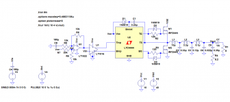
I've made 3 simple circuits in LTSpice to test based on your suggestions and Bob Codells chapters about class D amplifiers. I'm using LTC4444 to simulate the gate driver circuit, but I'm having some problems, I can't simulate the 2 amplifiers with feedback, the simulation takes too long and I don't know why, another problem is an offset of almost 1V present at the output and I also have high THD levels (0.7% delivering 14 W). Can anyone help me here?
In real life what could be a good gate driver circuit?
PS:
Attached the files and pictures of the circuits.
Best regards,
Daniel
Attachments
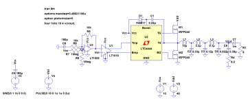
Ok, first of all IRFP240 have a huge die, and as such, a huge input capacitance, and they're quite slow by today's standards (at least regarding the reverse recovery time of the body diode).
Second, i don't see any gate resistors between the FET driver and the FETs. You need these to limit the rise times of the FETs, and these can also be used for dead-time adjustment. Dead-time's needed to avoid shoot-through (when both FETs are conducting, and as such, the power supply's shorted) - this can and WILL blow the FETs and possibly cause some damage in the power supply as well. It's quite customary to include reverse-diodes in parallel with the gate resistors ("pointing" away from the FETs) - you want to limit the turn-on time of the FET, but you want it to turn off as quickly as practically possible.
Thirdly - 10v is a little bit low for the gate drive of a FET. Yes, the specs in the datasheets are indeed measured with 10v in the gate, but you could easily push that up to 12-15v (or whatever's within the limits of your gate driver), and get lower Rds(on) in the FETs.
Fourthly(?) - you might want to NOT start the data-saving in the same instant as the sim starts. It might take a few miliseconds for the power supplies, the amp itself and the oscillation to stabilize, and that can easily skew the THD measurement results 🙂
You might want to subscribe to the LTspice Yahoo group - they have a pretty comprehensive library of models.
Disclaimer: In case i've made any inaccurate statements, i'm more than open to corrections from more knowledgeable members 😀
IRFB4019 are good common class d mosfets with low C.
Try 10R gate resistors with fast diodes discharging the gate.
There is the irs2092 solution but I wouldn't recommend it for beginners.
It is so fussy about pcb layout and decoupling.
On the other hand IR do the iraudamp9 which comes with schematic and pcb layout already done for you.
Try 10R gate resistors with fast diodes discharging the gate.
There is the irs2092 solution but I wouldn't recommend it for beginners.
It is so fussy about pcb layout and decoupling.
On the other hand IR do the iraudamp9 which comes with schematic and pcb layout already done for you.
Thank you all for your great help,
I will take a look at IRAUDAMP 9 😉
10R gate resistors seems a good idea but there is any way to calculate the gate stopper resistors, based on the time constant given by RC.
Which diodes I should use to discharge the gates?
Best regards,
Daniel
I will take a look at IRAUDAMP 9 😉
10R gate resistors seems a good idea but there is any way to calculate the gate stopper resistors, based on the time constant given by RC.
Which diodes I should use to discharge the gates?
Best regards,
Daniel
Which diodes I should use to discharge the gates?
Best regards,
Daniel
I use Stth1r02 fast diodes.
I everyone and thank you very much for your help,
LTSpice doesn't have that specific diode and I don't know how to add it.
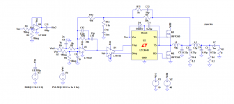
I also don't have that kind of MOSFET devices, I'm still using IRFP240, and I've added 10R resistors and 1N5819 as gate diodes, but now I can't simulate the circuit because simulation takes to long, I've tried to start the saving time at 100 ms but the problem remains, I've also tried without the diodes and with lower gate resistor values, but the problem persists.
I really need help here.
PS:
LTSpice circuit attached.
Best regards,
Daniel
LTSpice doesn't have that specific diode and I don't know how to add it.
I also don't have that kind of MOSFET devices, I'm still using IRFP240, and I've added 10R resistors and 1N5819 as gate diodes, but now I can't simulate the circuit because simulation takes to long, I've tried to start the saving time at 100 ms but the problem remains, I've also tried without the diodes and with lower gate resistor values, but the problem persists.
I really need help here.
PS:
LTSpice circuit attached.
Best regards,
Daniel
Attachments
What exactly does "too long" mean to you?
Anyway, i changed a few of those Spice directives, and the sim takes a "normal" amount of time, considering we're dealing with high-frequency stuff here.
Point no.1: literally NO dead-time at the outputs of the LT1016 - the two signals intersect around the mid-point of their low-to-high / high-to-low transitions. That's bad, for reasons i've stated in a previous post.
Point no.2: With a 1kHz input signal, there's nothing resembing that, at the output. I just found the reason - the ouput of U3 sits at about 5.5v DC. I thought there was something odd with that divider with 1meg resistors...
The end of C8 that goes to ground, should be going to the midpoint of that Vcc splitter, actually. And the input signal just goes through a cap, to the In+ of the opamp, with a resistor from there to the mid-point of the Vcc splitter.
http://www.eng.yale.edu/ee-labs/morse/compo/sloa058.pdf
It kinda-sorta works now, but it'll take a while for the input / output caps to charge. On an i7-2720qm, this 6ms sim took 360 seconds, as per the Spice error log.
You're gonna wanna fiddle around with the gain and offset of that opamp stage. If you plot Vtri, and the output of that opamp, you'll see why 😀
Attachments
Correction: i removed C8 and added a resistor from Vin to the Vcc splitter midpoint ("virtual ground").
Thank you very much for your great help, sorry for answering so late,
What I should do to add some dead time?
Why the LT1016 comparator output saturates at about 5V?
What is the midpoint I should use for the opamp? 5V?
I didn't understand the changes you've made, could you explain it better to me please?
PS: Do you know any easy way to mute the input of an audio amp, without using any IC or potentiometer, without changing the DC bias point, and pop free?
Sorry for answering so late,
Best regards,
Daniel
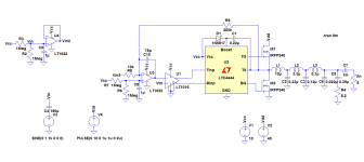
Why this circuit doesn't work?
Why the output wave of U3 is so strange?
Can you help me here, please?
Why the output wave of U3 is so strange?
Can you help me here, please?
Attachments
Last edited:
Hi everyone,
I need help! I'm having some problems because it's very difficult to adjust the DC offset at the output and the other problem is the shoot-through. I need to add some dead time but I'm new at class D and I don't know which components I should add (I'm using LTSpice and I only have some components). I also need some form of feedback in my amplifier, can you give me some suggestions on how to do this, please?
Best regards,
Daniel
Attachments
Something's still very wrong here. Have you tried plotting the output of U3? That's very definitely not right.
And if by "DC offset at the output" you mean the Vout signal, that's inherently gonna have DC offset (ideally at 1/2 of Vdd), since this is a single-supply amp 🙂 I mean, why is C7 there?
Hmm... Just for kicks, i disconnected the opamp output from the comparator input. The opamp output is a nice sine wave, as you'd expect, but the unconnected input of the comparator (i repeat, INPUT), apparently has some sort of high-duty-cycle square wave on it.
Hi everyone,
Thank you very much Khron for your help.
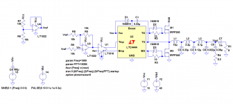
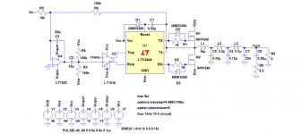
Can you take a look at this class D amplifier using negative feedback, do you know how to calculate the integrator capacitor?
This design seems to have problems with the output stage, maybe shoot-through, but I don't know why, LTC4444 should protect the output MOSFETs like it's said in the app note. Without the schottky diode and the resistor the amplifier doesn't work. Why?
Best regards,
Daniel
Thank you very much Khron for your help.
Can you take a look at this class D amplifier using negative feedback, do you know how to calculate the integrator capacitor?
This design seems to have problems with the output stage, maybe shoot-through, but I don't know why, LTC4444 should protect the output MOSFETs like it's said in the app note. Without the schottky diode and the resistor the amplifier doesn't work. Why?
Best regards,
Daniel
Attachments

I've made some changes, I wanted to know why the output devices are dissipating so much power, and why there are reversed currents at the output devices, can you help me here?
The distortion is high it's always between 0.7 and 1%.
I wanted to make some protection circuits, I know that I can use a relay to disconnect the output of the amplifier and I can use two relays to disconnect the supplies if the amplifier overheats, but what is/are the circuit(s) I should use for S/C protection? 😕
It's possible to limit the current at the rails to avoid shoot-through damage?
Best regards,
Daniel
Attachments
- Status
- Not open for further replies.
- Home
- Amplifiers
- Class D
- Simple Class D Project