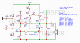
I want a relatively high efficiency amplifier design with a simple design. I created a circuit by examining some circuits on Tubecad pages. But I have no idea how much power the LM337 can provide.
How much power can be safely received from a single LM337?
Which would be a better idea to use pass transistor or parallel LM337 to increase power?
I'm waiting for your opinions about the circuit.

How much power can be safely received from a single LM337?
Which would be a better idea to use pass transistor or parallel LM337 to increase power?
I'm waiting for your opinions about the circuit.
Good idea.
It will work.
LM337T is a TO-220.
As far as I remember LM337T can take 1.5A.
Of course you have to use fairly large heatsink for the transistor and the LM337.
Class A generates heat.
It will work.
LM337T is a TO-220.
As far as I remember LM337T can take 1.5A.
Of course you have to use fairly large heatsink for the transistor and the LM337.
Class A generates heat.
Single ended class A, as shown, is the least efficient of all the amplifier classes.
It's actually push-pull, similar to an SRPP stage but in class A. The voltage across R1 and R4 together is kept constant by the regulator, so the current through R4 must decrease when the current through R1 increases.
Neat, but how do you prevent/adjust dc on the output. Right after turn on will be settling while cold, may expose speakers to dc.I want a relatively high efficiency amplifier design with a simple design. I created a circuit by examining some circuits on Tubecad pages. But I have no idea how much power the LM337 can provide.
How much power can be safely received from a single LM337?
Which would be a better idea to use pass transistor or parallel LM337 to increase power?
I'm waiting for your opinions about the circuit.
View attachment 1246470
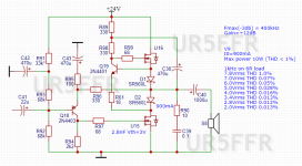
It seems to me that the distortion level of your amplifier is too high. This may be a consequence of computer modeling and imperfect models, but usually in practice the distortions will be even higher. I recently experimented with a similar circuit design here. I have not used LM337. To stabilize the output stage current, I used a simple circuit with two transistors. I got ten times less distortion than in your circuit - 0.014% with an output power of 2W. Here is this version of the diagram:

But as a result, I abandoned the circuit that uses resistors in the output stage as current sensors. Replacing them with Schottky diodes turned out to be more successful - with the same distortions, such a replacement allows one to obtain greater output power at the same supply voltage.

The circuit with Schottky diodes also has the advantage that it can work not only in class A, but also in classes AB and B. You can set any quiescent current of the output stage. Now this circuit works in my AB class with a quiescent current of 450 mA. This provides a balance between efficiency and quality. I'm very pleased with the results and the amp sounds very good.
I will follow your thread. I would be interested to know the results if you assemble your amplifier with an LM337 and measure its distortion. Perhaps everything will turn out to be much better than in the simulation. Or perhaps not. In any case, the result will be interesting

But as a result, I abandoned the circuit that uses resistors in the output stage as current sensors. Replacing them with Schottky diodes turned out to be more successful - with the same distortions, such a replacement allows one to obtain greater output power at the same supply voltage.

The circuit with Schottky diodes also has the advantage that it can work not only in class A, but also in classes AB and B. You can set any quiescent current of the output stage. Now this circuit works in my AB class with a quiescent current of 450 mA. This provides a balance between efficiency and quality. I'm very pleased with the results and the amp sounds very good.
I will follow your thread. I would be interested to know the results if you assemble your amplifier with an LM337 and measure its distortion. Perhaps everything will turn out to be much better than in the simulation. Or perhaps not. In any case, the result will be interesting
Here are some ideas to make class A more efficient (or less inefficient rather!):
https://www.diyaudio.com/community/threads/se-class-a-regulator-chip-amp-madness.192934/post-2644595
https://www.diyaudio.com/community/...the-complementary-version.193214/post-2649553
https://www.diyaudio.com/community/threads/se-class-a-regulator-chip-amp-madness.192934/post-2644595
https://www.diyaudio.com/community/...the-complementary-version.193214/post-2649553
- Home
- Amplifiers
- Solid State
- Simple Class A Amplifier