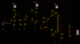
AFAIK, there is no restriction on posting the below circuit, found in the public pages on Elliott Sound Products, as part of the P12 project description.
Looks simple (maybe deceptively so), and easy to build. Came up in a post in Sakis' P3A Comparison thread. I just finished assembling the boards for the P3A amp from the same web site (which sounds quite good btw), and just wondering if anyone has tried building this or something similar, or have any comments about how well this might work (or might not... 😀).
 please see the schematic in the link below
Original article link: Simple 60 Watt Power Amplifier
Looks simple (maybe deceptively so), and easy to build. Came up in a post in Sakis' P3A Comparison thread. I just finished assembling the boards for the P3A amp from the same web site (which sounds quite good btw), and just wondering if anyone has tried building this or something similar, or have any comments about how well this might work (or might not... 😀).
please see the schematic in the link below Original article link: Simple 60 Watt Power Amplifier
Last edited by a moderator:
Its a minimal design for an amplifier.
Its more usual to see an LTP on the front end with constant current source and current mirror.
Its more usual to see an LTP on the front end with constant current source and current mirror.
Yes, his other designs use LTP in the input, and he does say this is an old design, and shows the evolution across three examples. I guess I was just wondering if there was something not so obvious to a casual observer (like me).Its a minimal design for an amplifier.
Its more usual to see an LTP on the front end with constant current source and current mirror.
I wonder if I'm missing something, or a component is missing from the schematic...
R4 needs about 0.6 volts across it...that means that R5 should have about
10/2.2*0.6=2.73 volts. That means (if you want the ouput quiescent voltage to be zero) that the voltage on the base would have to be about 2.73+0.6=3.33 Volts. Assume Q1 has a beta of 200, then the drop across R3 would be 27000*0.6/2200/200=0.037 Volts, so the total voltage at the wiper would need to be 3.37 volts. An LED with reasonable currents through it only has about 1.8 volts across it. Thus, you could never get the output offset voltage to zero with this arrangement.
I will note that Rod Elliot does say:
"Please: bear in mind that these are all theoretical circuits - the designs are sound (pun intended) and have been simulated, but they have not been built at this stage. I have no reason to suspect that the designs as shown will not work perfectly - or as perfectly as they will work (que?) - but I would not be happy without providing this warning. "
So, please be careful if you build these.
I wonder if I'm missing something, or a component is missing from the schematic...
R4 needs about 0.6 volts across it...that means that R5 should have about
10/2.2*0.6=2.73 volts. That means (if you want the ouput quiescent voltage to be zero) that the voltage on the base would have to be about 2.73+0.6=3.33 Volts. Assume Q1 has a beta of 200, then the drop across R3 would be 27000*0.6/2200/200=0.037 Volts, so the total voltage at the wiper would need to be 3.37 volts. An LED with reasonable currents through it only has about 1.8 volts across it. Thus, you could never get the output offset voltage to zero with this arrangement.
I will note that Rod Elliot does say:
"Please: bear in mind that these are all theoretical circuits - the designs are sound (pun intended) and have been simulated, but they have not been built at this stage. I have no reason to suspect that the designs as shown will not work perfectly - or as perfectly as they will work (que?) - but I would not be happy without providing this warning. "
So, please be careful if you build these.
Could we keep the parts values but put blue LED instead of green?
Could we keep the parts values but put blue LED instead of green?
I guess that would work, so long as the blue LEDs operate with about 4 Volts across them (that would give a little bit of margin). I don't think that their "on" voltage is that different from green...Do you have a table and some typical values for the various colors?
I was thinking that maybe 2 (or perhaps 3) LEDs in series would give enough voltage to get the balance right...
I am going to build something similar for a BI-amp project.
The sound from this kind of amplifier can be very good, and in my opinion rival modern designs as well.
It is not flawless in distortion figures and getting the output at ±0 volts is not easy and keeping it there isn't either, but this kind of amplifier can be remarkably stable and easy to build -- even scrap-heap spaghetti wiring it and mounting it on a piece of cardboard wont kick this thing into oscillation.
Well thats the experience i have with this kind of circuit.
I solved the DC offset by making it a single rail amplifier -- using high quality output capacitors wont affect the sound much (inaudible in my opinion).
See my implementation below:
Attachments
There were many integrated (pre- and power amplifier in one unit) which had a similar power amplifier section produced in 1970-ties. I owned one of them, Leak Delta 30 (a whopping 15+15 watts into 8 ohms!). You can find circuits on the web, or in a book like "Valve & Transistor Audio Amplifiers" by John Lindsley Hood. It has the circuit of the Leak delta 70, a whopping 35 + 35 watts into 8 ohms, you will not notice the difference.
The question You have to ask Your self is Why? Why not just buy any contemporary amp. The people who constructed, produced and sold those amps to the public have all moved on.
The one I owned was not a bad amplifier, all the latter once I owned have been better, but not by much.
The question You have to ask Your self is Why? Why not just buy any contemporary amp. The people who constructed, produced and sold those amps to the public have all moved on.
The one I owned was not a bad amplifier, all the latter once I owned have been better, but not by much.
It's actually *simpler* to add an extra input transistor wired as a differential pair, and skip the Led/trimmer/extra resistors and caps, etc.
Fair Q... A: I would say, why not? For me, diy is a hobby. Does not even have to be the best in its class. That almost misses the point for me. If I have to worry if the competition is a smidgen better (meaning like 0.01 thd v. 0.001thd), it stops being fun, and starts being work. I have had more than one "contemporary" amp, still have a couple, and some sound quite nice (to me, anyway). Some, sadly, do not, using many more parts....You have to ask Your self is Why? Why not just buy any contemporary amp...
@ Captain A.: Nice. Btw, in the article, Rod's circuit started single rail.
@JMFahey: I would say that if you end up with a same/lower parts count, that would be great. That might change the intent of the original idea too much.
@djoffe: I suppose it really calls for a zener, not LED...🙁
In fact LEDs are the ultimate choice for this particular task in Rod Elliott's circuit. I found somewhere, but can not remember exactly where, that LEDs have the best temeperature stability for this kind of DC offset setting.
Putting a driver in would be awfully tempting, especially using those two old warhorses on the CFP. It would do wonders for the distortion figures and take a lot of load off the VAS.
Personally I would scrap that design and go for a full implementation of a class AB amp.
I use LTP with CM and CCS. VAS with Vbe multiplier and CCS.
Driver stage into multiple output transistors.
I use LTP with CM and CCS. VAS with Vbe multiplier and CCS.
Driver stage into multiple output transistors.
I was curious about forward voltage of blue LEDs...so I took an unscientific sample of 1 data sheet...Kingbright Part Number: AA2214QBS/D Blue.
It showed forward voltage at 5 mA of 2.8 Volts. So, in this application, it wouldn't quite work. Perhaps other blue LED's have a bit higher forward voltage.
If you could use an LED or LEDs, it's much preferable to a zener from a noise standpoint.
Regarding tempcos...a green LED and a 2N3904, run at the correct current densities, have a very low tempco voltage output, right around 1.2 Volts, and very low noise.
ivanlukic,
The Blue LED you've found does indeed have a forward voltage of 3.8 Volts nominal at If=20 mA. In this circuit, the LED operates at about 1 mA. That would put the voltage at around 3.25 volts...still just a little bit low.
It looks like if you were willing to run 5 mA through the diode you could just about get there.
Do you have any info on the tempco of the Blue LEDs? I didn't see anything on the data sheet.
Thanks...
Dan
ivanlukic,
The Blue LED you've found does indeed have a forward voltage of 3.8 Volts nominal at If=20 mA. In this circuit, the LED operates at about 1 mA. That would put the voltage at around 3.25 volts...still just a little bit low.
It looks like if you were willing to run 5 mA through the diode you could just about get there.
Do you have any info on the tempco of the Blue LEDs? I didn't see anything on the data sheet.
Thanks...
Dan
If I found blue leds with more than 4V forward voltage and tempco data I shall post.
- Status
- Not open for further replies.
- Home
- Amplifiers
- Solid State
- "Simple" CF amplifier circuit...