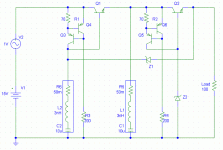
No I don't have any model to advice.
Your CSSs seem to run at 10mA, that's a bit high for a CRD. But I've read here that 4mA is a good value for biasing a zener. You could try so.
Don't forget that a CRD is just a selected Jfef with the gate connected to the source
Your CSSs seem to run at 10mA, that's a bit high for a CRD. But I've read here that 4mA is a good value for biasing a zener. You could try so.
Don't forget that a CRD is just a selected Jfef with the gate connected to the source
What if you would connect zenerdiode Z1 to ground (Z1 should be greater then Z2) and remove C2....
Ultima Thule said:What if you would connect zenerdiode Z1 to ground (Z1 should be greater then Z2) and remove C2....
...kind of missing the point of a "cascoded regulator".
Changing the configuration to that which you suggested would make the circuit a simple zener regulater (albeit a cascaded one) - and not in any way a cascoded circuit.
Although the names are similar they have pretty much nothing in common.
Any other suggestions?

🙁
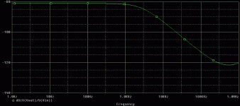
(sorry, but I just wanted to try that picture out 😉 )
Not bad, isn't it? Better than I thought it would be.
On the CR diodes, be sure to increase the input headroom, these things need at least 5V or more to work well. And as said, they are limited to 4 or 5mA. A good first approximation is a current source of say 5mA paralleled by a resistor of 100k.
One measurement I haven't seen is the output impedance. That is also quite importance, because it determines the output ripple resulting from the varying load current with freq.
What you could do is inject an AC current into the output (not exceeding the DC load current of course) via a large isolating cap, and then see what the resulting output signal is. Ideally, if the output impedance was zero, it would be zero volts. It won't be, but it is an important regulator performance indicator.
If it rises with freq (which it will) you can try output capacitors.
Jan Didden
annex666 said:
...kind of missing the point of a "cascoded regulator".
Any other suggestions?
No, but a question! 😀
What is the point with a cascoded regulator?
Does it matter wethere it is a cascode or cascade?
How would my suggestion perform if you simulated it?
Thanks for your time! 😉
If you want (in this case) the cascode is a cascade, but with the 1st reg having (in exemple) +5V compared to the 2nd stage's output
and not a fixed voltage to ground, in a cascaded configuration
and not a fixed voltage to ground, in a cascaded configuration
Ok guys, I've just come home from uni and had a bit of a relax for the evening.
Term has just finished for easter so I'll be taking it easy for a few days.
I'll try and make up a few schematics of different topologies and compare the results.
The suggestion you made about using two zener regulators has been done (tried and tested you may say) - if you've got a certain circuit that works well why not just shove two in series, results are almost guaranteed to improve by an order of magnitude. The point I was trying to introduce was that I had an idea - i.e. the cascoding of the output transistor and sourcing the zener current from within the cascode loop to better reject input fluctuations and was wondering what people thought of the idea.
Indeed I have tested a circuit much like the one you state that uses burried zeners (pretty sure that's the wrong term) and it works incredibly well, although the simulation software I had then was far inferior to PSpice so I can not be sure until I re-simulate it.
I'll post a picture of that too once I get the time and hopefully some sims. too.
In the meantime I openly invite anyone to post their own regulator designs and specs. if possible.
Thank you once again one and all for posting.
Some people seem keen on using LED's as voltage references for the current sources any thoughts on using that?
Added in edit:
Another question is it the PSRR that is the most important parameter for testing the regulator?
I have tried using a current sink as load where i sweep the frequency and check the output impedance. If you do that what is the criteria for good performance, straigth output impedance up to infinity or as low as possible?
- Status
- Not open for further replies.
- Home
- Amplifiers
- Solid State
- Simple Cascoded Regulator

