Folks:
I'm no engineer, as we may well soon conclusively determine, and I could use some oversight. I would like to include a bi-color LED as a power indicator in a preamp project and would appreciate some guidance on the circuit I've cobbled together.
A few things to note:
1. The bipolar power supply should be assumed to be always on.
2. The preamp power supply will be off when the preamp is in "standby" mode and on when the preamp is in its "on" mode.
3. The bi-color LED is a two legged device.
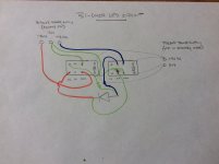
My concern with this design is that a short circuit might exist in the brief moment when the preamp power supply is switching between its "on" and "standby" states.
What I like about this circuit is that it's pretty simple, consisting of just five parts (2 relays, 2 resistors and the LED). But will it work properly over the long run and is there a better, more reliable and efficient design?
All input is appreciated.
Regards,
Scott
I'm no engineer, as we may well soon conclusively determine, and I could use some oversight. I would like to include a bi-color LED as a power indicator in a preamp project and would appreciate some guidance on the circuit I've cobbled together.
A few things to note:
1. The bipolar power supply should be assumed to be always on.
2. The preamp power supply will be off when the preamp is in "standby" mode and on when the preamp is in its "on" mode.
3. The bi-color LED is a two legged device.
My concern with this design is that a short circuit might exist in the brief moment when the preamp power supply is switching between its "on" and "standby" states.
What I like about this circuit is that it's pretty simple, consisting of just five parts (2 relays, 2 resistors and the LED). But will it work properly over the long run and is there a better, more reliable and efficient design?
All input is appreciated.
Regards,
Scott
Attachments
It would help if you made a schematic instead. Usually relays are break before make.
Bicolor LEDs have three leads, one is the common cathode.
Bicolor LEDs have three leads, one is the common cathode.
Rayma:
Thanks for the quick response and sorry for the sloppy picture. Okay, I will try to make a schematic and add it to this thread. I'm not sure where to begin, but I'll start muddling on that.
I have about 100 two-legged Blue/Red LEDs in my parts bin. They work just fine. Now that I think about it, I can imagine a design consisting of just one relay, a three-legged bi-color LED and a resistor that would likely work in my situation. But since I don't have any three-legged bi-color LEDs on hand, I'd like to concentrate on an evaluation of the circuit I've already presented.
Regards,
Scott
I have about 100 two-legged Blue/Red LEDs in my parts bin.
Ok, those LEDs must be in antiparallel instead of having a common cathode.
They should be easy to work with, since you only need to reverse the supply polarity to light/dim them.
I would think you could get by with only one dropping resistor. Just connect the LED and resistor in series,
and treat them as a single part. You are trying to indicate when BOTH 15V supplies are on, or not?
Last edited:
Bicolor LEDs with two leads illuminate one LED with current in one direction, and the other LED with current in the other direction. Your circuit as shown applies current of the same polarity regardless of the relays' positions.
Assuming that you wish to have the two colors indicate 'Standby' and 'On', you can eliminate one relay and one resistor. Your relay is DPDT; connect each COM pin to one leg of the LED, with one resistor in series with the LED. On one side, connect the NO contact to GND and the NC to a supply rail; on the other side, connect the NC contact to GND and the NO contact to the other rail.
You could, if you chose, put a resistor in series between each rail and the relay, and eliminate the one in series with the LED. That would give you the ability to set the current for each color independently, in case they have different Vf (they do) and differing luminous efficiencies (also highly probable). The additional cost / space for a second resistor probably pales in comparison to the benefits of losing the 2nd relay.
Last edited:
Relays are very messy and power hungry. One opamp used as a comparator will do this.
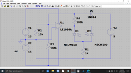
This is an outline of a working circuit. You may need to consider the reverse breakdown voltage of the LED's and either add a couple of zeners and IN4148's. You could perhaps add this to the series feed resistor for the LED and thereby get control of the individual brightness levels as well.
When the voltage of V3 (the 5 volt supply) changes from 0V to 5V then the opamp switches polarity at its output.
It relies on the supplies having a common connection.
If they do not then its still easily doable by the addition of a simple optocoupler.
Attachments
You failed to explain the most important aspect: how exactly do you want the LED(s) to behave under various conditions: one supply absent, two supplies absent, etc.Folks:
I'm no engineer, as we may well soon conclusively determine, and I could use some oversight. I would like to include a bi-color LED as a power indicator in a preamp project and would appreciate some guidance on the circuit I've cobbled together.
A few things to note:
1. The bipolar power supply should be assumed to be always on.
2. The preamp power supply will be off when the preamp is in "standby" mode and on when the preamp is in its "on" mode.
3. The bi-color LED is a two legged device.
My concern with this design is that a short circuit might exist in the brief moment when the preamp power supply is switching between its "on" and "standby" states.
What I like about this circuit is that it's pretty simple, consisting of just five parts (2 relays, 2 resistors and the LED). But will it work properly over the long run and is there a better, more reliable and efficient design?
All input is appreciated.
Regards,
Scott
OK, the bipolar supply is assumed to be always on and OK, but even that leaves a number of options.
If you manage to state unambiguously what you want, there are chances we can come up with a reasonable solution (diodes + resistors for example).
Relays for such a problem are utter madness and overkill
Folks:
Ooof! It seems I've opened a can of worms here. Please be gentle -- in a perfect world, the solution to my problem will be a simple one.
Elvee: Okay, the preamp will be a two-chassis affair. The power supplies will be in one of the boxes and the preamp (Wayne Colburn's BA18 line stage and a source selection / attenuation /display system) in the other box. The source / attenuation / display system has a 5V DC out when the system is in its "on" mode. I'd like the bi-color LED to be red (5 or 6 ma) when the bipolar power supply is plugged in and the preamp is turned off (i.e., in standby mode). When the preamp is "on" and the 5V out is active, I'd like the bi-color LED to be blue (6 to 8 ma).
Mooly: I think so. One of the bipolar power supplies in the remote chassis will be supplying the +/- 15V DC used to power the source selection / attenuator / display system which will provide the 5V DC out.
rco3: No disrespect intended, but I don't think that's correct. But assuming you are right, then I'd be happy to reverse the wiring from one of the relays to the LED if that resolves the issue.
rco3: Ah, yes, this is excellent and a clear improvement over my design.
Mooly: Your solution may be ideal but to a layman such as myself it seems vastly more complicated than the one relay / two resistor alternative. A single relay doesn't draw very much current and since most of the time it will be in "off" mode I expect it will last a very long time. I'm not trying to start an argument but in this case, simpler is a whole lot better for me unless there is a compelling reason to devise a more elegant design. Do you believe that the relay design is a poor solution for me?
All:
Seriously, thanks for the guidance. I may actually learn something useful from this.
Regards,
Scott
Ooof! It seems I've opened a can of worms here. Please be gentle -- in a perfect world, the solution to my problem will be a simple one.
You failed to explain the most important aspect: how exactly do you want the LED(s) to behave under various conditions: one supply absent, two supplies absent, etc.
Elvee: Okay, the preamp will be a two-chassis affair. The power supplies will be in one of the boxes and the preamp (Wayne Colburn's BA18 line stage and a source selection / attenuation /display system) in the other box. The source / attenuation / display system has a 5V DC out when the system is in its "on" mode. I'd like the bi-color LED to be red (5 or 6 ma) when the bipolar power supply is plugged in and the preamp is turned off (i.e., in standby mode). When the preamp is "on" and the 5V out is active, I'd like the bi-color LED to be blue (6 to 8 ma).
Does the 5 volt supply 0V line have electrical continuity to the 0 point of the -/+15 v supply?
Mooly: I think so. One of the bipolar power supplies in the remote chassis will be supplying the +/- 15V DC used to power the source selection / attenuator / display system which will provide the 5V DC out.
Your circuit as shown applies current of the same polarity regardless of the relays' positions.
rco3: No disrespect intended, but I don't think that's correct. But assuming you are right, then I'd be happy to reverse the wiring from one of the relays to the LED if that resolves the issue.
Assuming that you wish to have the two colors indicate 'Standby' and 'On', you can eliminate one relay and one resistor. Your relay is DPDT; connect each COM pin to one leg of the LED, with one resistor in series with the LED. On one side, connect the NO contact to GND and the NC to a supply rail; on the other side, connect the NC contact to GND and the NO contact to the other rail.
rco3: Ah, yes, this is excellent and a clear improvement over my design.
Relays are very messy and power hungry. One opamp used as a comparator will do this.
This is an outline of a working circuit. You may need to consider the reverse breakdown voltage of the LED's and either add a couple of zeners and IN4148's. You could perhaps add this to the series feed resistor for the LED and thereby get control of the individual brightness levels as well.
When the voltage of V3 (the 5 volt supply) changes from 0V to 5V then the opamp switches polarity at its output.
It relies on the supplies having a common connection.
If they do not then its still easily doable by the addition of a simple optocoupler.
Mooly: Your solution may be ideal but to a layman such as myself it seems vastly more complicated than the one relay / two resistor alternative. A single relay doesn't draw very much current and since most of the time it will be in "off" mode I expect it will last a very long time. I'm not trying to start an argument but in this case, simpler is a whole lot better for me unless there is a compelling reason to devise a more elegant design. Do you believe that the relay design is a poor solution for me?
All:
Seriously, thanks for the guidance. I may actually learn something useful from this.
Regards,
Scott
I don't know what parts, resources, real estate, etc. are available for your circuit, so I'm not making suggestions for other strategies to follow - I assume you've chosen these parts because they are available. I agree that a relay is power hungry and brute-forcey; it is also, as SRMcGee points out, a very simple solution to implement, once, with minimal component count.
SRMcGee: when your circuit is in the NO position (both relays are driven by the same signal in parallel), you have the +15 rail connected to the anode and the cathode to ground. Anode more positive than cathode causes current to flow in the forward direction of the diode shown (the anti-parallel diode wasn't shown). In the NC position, the anode is now tied to ground and the cathode is tied to -15V, causing current to again flow in the forward direction as the anode is again biased more positively than the cathode of the diode shown. The same LED will be illuminated in either position.
It is, of course, not necessary to use both rails to power this. In fact, my previous suggestion (shown as the middle schematic) made the same error - the same LED lit in both positions, because the relay action swapped both diode polarity and power polarity and you only want to swap one or the other. Oops. With two rails, you only need one pole - SPDT (or half the DPDT). Or, you can use one rail and a DPDT.
Last edited:
rco3:
Ahhh, ha! Yes, I understand. Three pictures really are worth a lot. Thank you!
All:
I'm still open to more elegant suggestions, subject to the limitation that I have little idea what it is that I am doing. I got into this hobby out of a love of music; the engineering side is still largely a mystery to me.
Thanks for the support.
Regards,
Scott
It would help if you made a schematic instead. Usually relays are break before make.
Bicolor LEDs have three leads, one is the common cathode.
Many but not all bicolor LEDs are 3 terminal but I used a 2 lead LED that started red, faded to off and
faded back up green. It monitored the temperature of a log transistor until it reached the servo controlled
operating temperature of 69°C. The device was a MAT-04 with 2 transistors as the heaters, 1 transistor as
the temperature sensor and the 4th transistor was the log device.
I used another 2 lead LED as the replacement for a grain of wheat pilot bulb in a Technics SH-9010 parametric
equalizer. The bulb was just 6.3V AC so the LED runs yellow behind the amber lens on the panel.
G²
Mooly: I think so. One of the bipolar power supplies in the remote chassis will be supplying the +/- 15V DC used to power the source selection / attenuator / display system which will provide the 5V DC out.
Mooly: Your solution may be ideal but to a layman such as myself it seems vastly more complicated than the one relay / two resistor alternative. A single relay doesn't draw very much current and since most of the time it will be in "off" mode I expect it will last a very long time. I'm not trying to start an argument but in this case, simpler is a whole lot better for me unless there is a compelling reason to devise a more elegant design. Do you believe that the relay design is a poor solution for me?
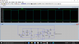
Its a bit clunky and inelegant and I'm going to say the idea by Itsmee is even better. That is super simple using just one transistor instead of an opamp.
I've added that design to the simulation to see how the resistor values effect the LED current.
You can not get any simpler than that. Just think of it as three resistors initially, forget the transistor you can add that later.
One practical point you should decide now is the value of resistors needed to get the brightness level you want.
Determine which colour of LED you want lit when the 5 volts is present and then measure the LED current with your chosen level of brightness. Also measure the voltage across the LED at this current.
Make a note of those two values.
Now do the same for the reverse direction, choose your brightness level and measure the current through and the voltage across the LED.
It's much easier to get resistor values correct this way than to faff about altering them when its all installed.
This shows Itsmee's solution where the LED current is equal for both directions and set at approx 8 milliamps. The graph shows the current in each LED. When one is on the other is off.
Attachments

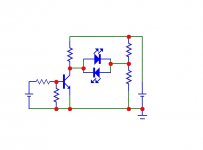
Here is a 1-transistor, 3-resistor solution.
The current in the LEDs can be adjusted via R2 (Red) and R1 (Blue).
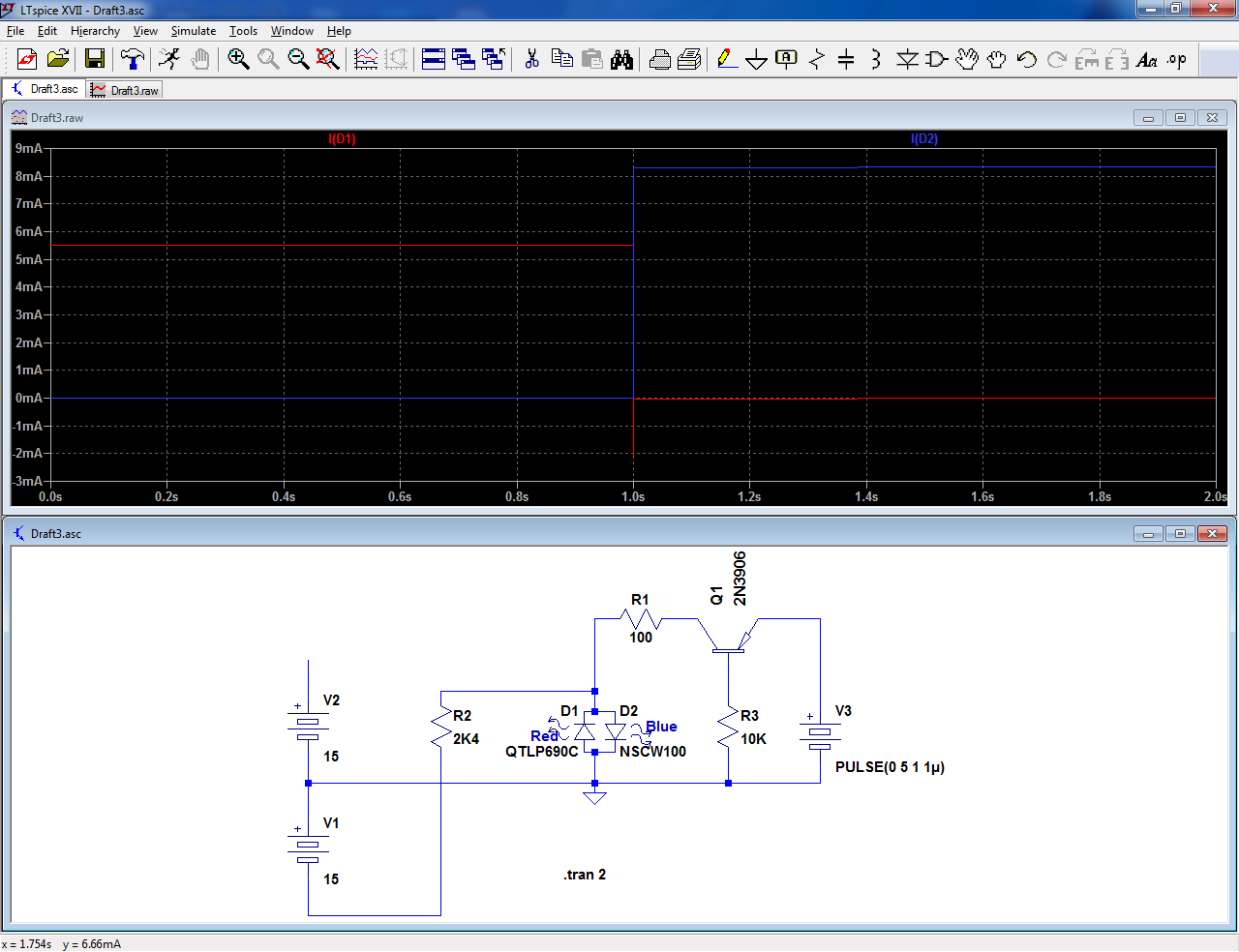
In principle, it is possible to use just 2 resistors and no transistor, but it requires a heavy quiescent dissipation.
If the transistor is a small PMOS, R3 can be omitted
The current in the LEDs can be adjusted via R2 (Red) and R1 (Blue).
In principle, it is possible to use just 2 resistors and no transistor, but it requires a heavy quiescent dissipation.
If the transistor is a small PMOS, R3 can be omitted
Attachments
If it makes things easier and perhaps displays more info, use another separate LED. Logic ICs can potentially do you some assistance. They have the power to feed LEDs.
Itsmee, Mooly and Elvee:
Many, many thanks! I think you've all provided the guidance I need (though I confess it will take a little time for me to fully appreciate how these circuits operate).
Regards,
Scott
Many, many thanks! I think you've all provided the guidance I need (though I confess it will take a little time for me to fully appreciate how these circuits operate).
Regards,
Scott
Yet another question: can I substitute a BC550 or BC556 for the 2N2222? I have plenty of the former and none of the latter on hand, and like to consume from my stockpile when possible.
Regards,
Scott
Regards,
Scott
Absolutely 🙂 Any small signal NPN transistor will do. It is simply used as a switch.
With no 5 volts present consider the transistor open circuit (not fitted).
With the 5 volts and it behaves like a short circuit between collector and emitter.
With no 5 volts present consider the transistor open circuit (not fitted).
With the 5 volts and it behaves like a short circuit between collector and emitter.
- Home
- Design & Build
- Parts
- Simple Bi-Color LED Circuit?