I may be wrong but ... no.
It looks like C3 is providing an a.c. short across the upper transistor.
Lose C3.
It looks like C3 is providing an a.c. short across the upper transistor.
Lose C3.
Also, it will be very difficult to achieve the correct biasing. One solution would be to use a Vbe (or Vgs) multiplier, mounted to the heatsink to allow thermal tracking.
Good luck!
Good luck!
The biasing difficulty is this.
With no input signal you, ideally, want the source voltage to be half the power rail, or 43V. The voltage across R2 will be about 0.6V. So the voltage across R3 will be 42.4V and the current through R3 will be 42.4/860k = 49uA. This current must be the sum of the current through R2 and the base current of Q3. R2's current is about 0.6V/56k = 11uA, so Q3 base current must be 38uA. So Q3's base current is dominating the current through R3. Now, Q3's collector current needs to be about 43/10k = 4.3mA. Knowing Q3's base and collector currents we can estimate it's beta to be 4.3m/38u = 113.
So the source voltage will sit at half the supply voltage only if the beta of Q3 is 113. The trouble is that the beta characteristic varies from one device to the next, often 50% or more, and within a single device it varies with Ic and temperature and Vce. So the odds of beta being 113 are very slim. If the beta was 50% out so would be your source voltage. You need a bias arrangement that is relatively insensitive to beta.
Ditto on the above. Also:
I would consider splitting R1 into two values and attaching the
+ terminal of the 100 uF cap between them for bootstrapping,
which is what might have originally been intended.
I would consider splitting R1 into two values and attaching the
+ terminal of the 100 uF cap between them for bootstrapping,
which is what might have originally been intended.
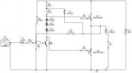
The three diodes aren't enough to bias the mosfets. You will need 4-6 volts (compared to 2.1 V) and some temperature compensation.
Per Anders is right. Use a Vbe multiplier as I suggested above, and mount it on the heatsinks. To address the bias stability of the input transistor as Traderbam noted, add an emitter resistor on the input transistor.
alternatively, you can use a pot in place of the three diodes to get this thing going. It wouldn't be able provide any thermal stability, which is critical in your design as there are no source resistors on Q3/Q4.
the voltage drop on R4/R7 is about 40v (86/2-3v for the Vgs drop on Q3). and you need about 6v drop on between the gates of Q3/Q4 so you need a pot about 6/40*(3300+3300) = 990ohm so a 1.5k pot should do.
I would strongly suggest a pair of source resistors.
the voltage drop on R4/R7 is about 40v (86/2-3v for the Vgs drop on Q3). and you need about 6v drop on between the gates of Q3/Q4 so you need a pot about 6/40*(3300+3300) = 990ohm so a 1.5k pot should do.
I would strongly suggest a pair of source resistors.
Have a look at SuperFlea:
http://www.diyaudio.com/forums/showthread.php?postid=68376#post68376
Just look at one half. Of course the ultimate in simplicity for a complementary design is the ZV5
http://www.diyaudio.com/forums/showthread.php?postid=68376#post68376
Just look at one half. Of course the ultimate in simplicity for a complementary design is the ZV5
Charles Hansen said:Per Anders is right. Use a Vbe multiplier as I suggested above, and mount it on the heatsinks. To address the bias stability of the input transistor as Traderbam noted, add an emitter resistor on the input transistor.
A Mosfet Vgs multiplier would be even more appropriate, and
consider some small output Source resistors, like .33 - .47 ohm.
Then, I think you'll have an amp. 😎
Hello Diode,
I wouldn't try to put vertical FETs in an amp designed for lateral FETs. The lateral FETs are still made. Hitachi split off their semiconductor division as Renesas. You can see their products at:
http://www.renesas.com/eng/products/discrete/transistor/index.html
Click on the link that says "Power MOSFET for General Amplifier". They don't make metal TO-3 packages any more, but they do make the plastic TO-3P (TO-247) packages.
Improved clones are also made in England by Magnatec:
http://www.magnatec-uk.co.uk/mosdata.shtml
These are available in both plastic and metal packages.
Hope this helps,
Charles Hansen
Charles:
Do you know of a Renasas distributor in the U.S.?
Ugh... I'm sorry, I just answered my own question. It looks like Arrow stocks them. $5 for 2SK1058's is pretty remarkable considering what some folks are selling NOS for.
Well, since I have you on the line...
I was reading your Balun article (Thanks!) I'd like to add some attenuation at the input of the receiver for speaker-level inputs (bal/unbal) for a distortion measuring rig. Do you know of any pitfalls in using dividers with these chips?
Believe it or not, there are two Charles Hansens in audio. I work for Ayre Acoustics and live in Colorado, and the other Charles Hansen lives back east and writes articles for AudioXpress. It's kind of confusing....
- Status
- Not open for further replies.
- Home
- Amplifiers
- Solid State
- simple amplifier with mosfets