So this is what I have so far, posted below. (Little Amp 1 Actual). I added the 270R, 4.7K and 500R pot as per wahab's suggestion. I started with a 1/2 Vcc of ~12V and a Iq of 1.5A and listened for a bit. At higher volumes it started to break up, more so in the low end. Over all, it sounded slightly duller and washy. I lowered the Iq to about ~.900A and Q3 collector to12V. It definitely sounded better. More solid bass and a more immediate sound overall. I'm just not sure about my process though. I have the 500R pot turned CCW all the way, which I guess is 500 ohms. I can't seem to get a lower Iq than .990A. Now for the question. I'm still confused about how to use ohm's law to determine the bias class determined by adjusting pot 1 and 2. For instance, what am I doing when I run the Iq at .460 amps as opposed to 1.5 amps? And does the 1/2 Vcc need to stay at 12V? Just can't seem to get over the hump on this.
Tom
(I need to order some BD139's and 140's so I can try Lazy Cats circuit)
Tom
(I need to order some BD139's and 140's so I can try Lazy Cats circuit)
Attachments
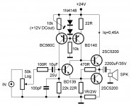
Well ,the components values were for a 12V PS , as in Godfrey s schematic.
For 24V both resistor and pots values should be increased two fold.
Also , i made the sim using 2SC5200 as output devices.
Quiescent current can be reduced by increasing proportionnaly
the 1R resistor but this will also reduce the total gain in inverse
proportion.
For 24V both resistor and pots values should be increased two fold.
Also , i made the sim using 2SC5200 as output devices.
Quiescent current can be reduced by increasing proportionnaly
the 1R resistor but this will also reduce the total gain in inverse
proportion.
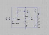
Giving in to the evil forces of negative feedback, and in the spirit of "how much fun can we have with three transistors", I'd like to add these two circuits to the pot.
The one on the left has high output impedance (low damping factor) and the one on the right has low output impedance (high damping factor).
In other respects the performance should be fairly similar. Being 3-stage amplifiers, there's enough feedback to get the distortion of both reasonably low. Hopefully the biasing of both circuits will sort itself out so that the power transistor runs at about 350mA, with about 6V on it's collector.
They won't go loud - maximum output power is about 1/4 Watt, but it may be interesting to compare them to see the effect of damping factor on sound quality.
p.s. That 2.67 Ohm resistor is a 2.2 Ohm resistor and a 0.47 Ohm resistor (which I think you have lying around) connected in series.
Attachments
Now for the question. I'm still confused about how to use ohm's law to determine the bias class determined by adjusting pot 1 and 2. For instance, what am I doing when I run the Iq at .460 amps as opposed to 1.5 amps? And does the 1/2 Vcc need to stay at 12V? Just can't seem to get over the hump on this.
The Ohm Law starts at the emiter of Q3.
BIAS CURRENT. How much current do you need to bias the output? Lets say you want as high as 900mA across emiter resistor. With 1R at Q3 emiter, you want the system to give you 900mV at the emiter (Ohm Law: V=I*R).
Assuming Q3 Vbe=650mV and Q1 Vbe=600mV, you want the base of Q1 to be = 600mV+650mV+900mV=2.15V. You get this voltage through the first potentiometer (U2) which acts as a voltage divider.
U2 is put between ground and a potential around 2.8 volt. So the base of Q1 can be biased from 0 to no more than 2.8 volt. The 2.8V is from 1N4148 forward voltage drop around 0.7 volt each (it works with the more or less 1k resistor to give a voltage drop).
VR1 can be set to give 2.8 volt to 0 volt at Q1 base. So theoretically you should be able to lower the bias current with VR1, but expect horrible signal with too low voltage.
THE OTHER BIAS RESISTORS. You should see U1 and R1 as ONE bias resistor, lets say Rb (The bootstrap cap will be more or less connected to the middle of it). This Rb sets the voltage at Q2 base, hence at the output (only differs around Vbe of 0.7v).
DO YOU NEED THE 0.5VCC OR THE 12V? May be not. There are at least 2 purposes of setting the output to 0.5Vcc.
Because the output voltage swing can never reach the supply rails, to maximize voltage swing you want the output to be centered at half Vcc. But in your schematic there is no high gain, so you wont be able to get +-10V anyway. Your gain is determined by transistor hfe (? I think so), so choose a high transconductance transistor such as TIP41C to get maximum output.
Another reason to have half Vcc at the output is to make both output transistors to work more or less like a push-pull where Q1 acts as a phase splitter. But low current will give you horrible distortion here, so class-A is mandatory, and with class-A you don't have to share the burden equally between Q2 and Q3. Q3 may take more the heat, and the output voltage can be closer to the rail (above 12V).
So it is okay to lower the Rb (and get higher than half Vcc at output) to get lower distortion.
Thanks Jay, I'll read through this a few times until it sinks in.
Hopefully the attached picture can make it clear.
I like this thread as I'm interested in high efficiency small quasi amp. But it seems mosfet is more suitable. For BJT, I'm interested with low power JLH. 2-3W JLH for example. Or the smallest possible without degrading too much of the quality (of course no more than 1A current).
Attachments
I like this thread as I'm interested in high efficiency small quasi amp.
Try to calculate all quiescent currents/potentials and edge currents that this circuit can provide to the 4 Ohm load. 😉
Attachments
Try to calculate all quiescent currents/potentials and edge currents that this circuit can provide to the 4 Ohm load. 😉
Why, is it good? 😀 I'm reluctant because this simple topology depends on the output device used, and I don't have the part (only fake ones) and the model for C5200. The input bias circuit is strange to me tho...
I have done quick sim for Tom's circuit with TO3 darlington output. 750mA, 17V at output, gives more than 4Vpp output with 0.5% THD. May be TIP47 (or TIP42?) will give better result?
- Status
- Not open for further replies.
- Home
- Amplifiers
- Solid State
- Simple amp circuit obsevations