Hi all,
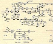
I was browsing trough my old socialist era magazines, Amaterske Radio, and found this simple active crossover. I am going to build it just for fun to hear how it sounds in comparison to other active line level crossovers I have. Please see the schematics and help me figure out the part values I need for 160-170 Hz crossover point.
Original uses 500 Hz with 18 dB/oct. I want to make the same slope, but 160-170 Hz approximately.
The R6 to R8 and C5 to C7 are low pass.
The R10 to R12 and C8 to C10 are high pass.
Thanks! I will let you know how it sounds.
Attachments
Last edited:
It´s quite simple. For decrease frequency, multiply cap values in the filter by the same amount. Or, increment the resistors in this network. Finally, an optional solution would be to increase the caps and resistor by sqrt of the needed frequency changes, f/e, for a decrement in 10 times the freq., increase R´s and C´s by sqrt of ten, or 3.16 to maintain the Q values.
Best regards.
Best regards.
Hi Osvaldo, thanks for the input...just to be clear, let say I want to lower the cut off frequency in half from the schematics, so I leave the resistors untouched, but double the filter capacitors.
Just to be exact, I would like to have formula to calculate it. I am not sure if I follow your second sentence...
Here in Linkwith page, the filter uses this formula for 12dB/oct:
Fp = 1/ (2PiRC)
Active Filters
However, later in the page the formula looks like this for 24 dB/oct:
Fp = 1/ (2.83PiRC)
Just to be exact, I would like to have formula to calculate it. I am not sure if I follow your second sentence...
Here in Linkwith page, the filter uses this formula for 12dB/oct:
Fp = 1/ (2PiRC)
Active Filters
However, later in the page the formula looks like this for 24 dB/oct:
Fp = 1/ (2.83PiRC)
I have finished the crossover, with the values adjusted for ~160 Hz crossover point. It works and sounds fine, I am quite happy with it, but the signal coming out is lot smaller than comming in. 2 volts on input will give me 0.4 volts on the out. Is there a way to increase signal coming out? Can I reduce or bypass R1 resistor?
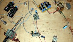
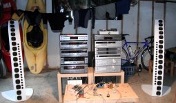
Currently I have this crossover folloved by JC2 preamp for high frequencies and NP10 preamp for low pass. Sounds wonderfull, but I want more gain, so the volume pot is not all the way up.
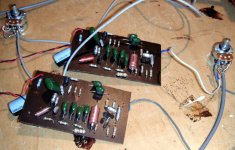
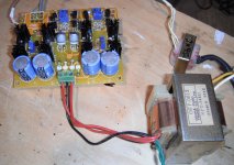
Thanks. I will post some pics when I come home.
Currently I have this crossover folloved by JC2 preamp for high frequencies and NP10 preamp for low pass. Sounds wonderfull, but I want more gain, so the volume pot is not all the way up.
Thanks. I will post some pics when I come home.
Yes, this resistor can be bypassed. But, in fact, it is better to attack filters with low impedance source, and load them with high impedance. So, I would suggest to move the input of the filter to the emiter of the first transistor, and eliminate all the collector components, and work it as a common collector stage.
In such a case, perhaps T2 must be re-biased.
In such a case, perhaps T2 must be re-biased.
Thanks Osvaldo for valuable comment. I bypassed the R1 resistor and the output signal jumped from 0.4 volt to 1.85 volt. Great, all the gain I need. No need for any other stages. After carefull listening I decided this is it and I will put it in the box. It already sounds better to commercial OPA based crossovers.
Modifiqueta
Only for curiosity, try getting the input from the emitter of the first transistor, and put temporarily a 10uF cap from collector to gnd. Perhaps the level will be further increased and distortion decreased.
As you say, the lower distortion is simply because of the signal passes though less stages. Take into account that every stage in the signal path adds its own small distortion, and following stages also adds distortion and amplifies the previous distorted signal, so the difference.
Sorry if my english isn´t too good.
Hi Osvaldo, your english is just fine. I know exactly what you are suggesting. I am already in the process of putting it in the box, so it may be late, but I will be building the same circuit again with better parts on better board, this was just a test. I will try to put the high pass arm of the filter on the emitor of T1 as you suggested. I am affraid that low pass would require more changes, so I will probably leave it.
Thnaks.
Thnaks.
OK, "yankee man". Good luck in the project. Also, you can try to replace the bjt with FET´s, improving noise and impedance matching.
I´m 42 years old, and "play" with electronics from my 16´s, when I made an entirely tube 80m ham emitter and receiver including self winded power and modulation transformers, and still make my own apparatus, and work in electronic equipments. I also can suggest only one thing: play and enjoy playing with electronics. So, make all trys and tests you want. No thing can give you a best satisfaction of have a thing made with your own hands, although the performance of such thing isn´t comparable with commercial ones. I can tell it from my own experience.
Good luck, and expect that "Yankee" not be offensive. Here in south america any US people ussualy are called "Yankees" although I ignore the mean of it.
Last edited:
- Status
- Not open for further replies.
- Home
- Source & Line
- Analog Line Level
- simple active crossover