You could go cheap with a motor run as the first cap and some salvaged computer switch mode parts for the second and third cap. (Not that you couldn't do better)
Just curious, 230V?
Just curious, 230V?
eeyore said:Here is my proposed PSU. The chokes are pretty cheap, and the 5U4G is pretty easily obtainable. The cap values are not too high, and can be easily found. I think that this PSU should be able to be built for aroudn US$100~150.
Note this will serve both channels. Also, I live in Australia so the primary is indicated as 230V/50Hz.
You should consider putting in a standby switch, or change tube rectifier to 5AR4 (and change your secondary voltage)
[OT]eeyore said:I thought that we [Australia] was moving to 230V +6%/-6%?
Thanks for the info.
BTW, I guess we haven't caught up yet. I just checked and found 252V.
[/OT]
Is dropping out another LC stage worth the saved money? From Partsconnexion, 1x Hammond 193H $26.42 and 1x JJ 220uF/385V $6.95, total savings of $33.37. A 10uF/600V solen is $5.50. A Hammond Universal 370FX (275-0-275 @ 150mA 5V ct @ 3A 6.3V ct @ 5A) is $79. 5AR4/5U4G around $10-20 new Russian/Chinese brands. However, NOS of 5U4G can be found for 'reasonable' price (for upgrades).
Total cost as above: US$150-170 depending on tube
Without the second LC: US$120-140.
(Obviously not including sockets, fuses, etc, etc... but this is just a first stab at it...)
From PSU2, with the above design the ripple after 10s is so small, it cannot display beyond 317.35 peak to peak, from zooming out and estimating, it might be 0.0025V. Without the second LC, after 10s, peak to peak is 321.06V to 320.98V or about 0.08V peak to peak, all of that (simulated) for only $33.37!
The specified DCR of the 193H is 65R.
If you go for CCS load on your 5842, the second L is optional as that stage will have a better PSRR.
If you go for a choke load, I'd keep the second L.
But your design goal is CCS, so there.
If you go for a choke load, I'd keep the second L.
But your design goal is CCS, so there.
eeyore said:From PSU2, with the above design the ripple after 10s is so small, it cannot display beyond 317.35 peak to peak, from zooming out and estimating, it might be 0.0025V.
set the reporting delay to 12 seconds or so
I did that, and it didn't change anything. Is there a way of making it display more than 3 decimal places?
eeyore said:Is dropping out another LC stage worth the saved money? From Partsconnexion, 1x Hammond 193H $26.42 and 1x JJ 220uF/385V $6.95, total savings of $33.37. A 10uF/600V solen is $5.50. A Hammond Universal 370FX (275-0-275 @ 150mA 5V ct @ 3A 6.3V ct @ 5A) is $79. 5AR4/5U4G around $10-20 new Russian/Chinese brands. However, NOS of 5U4G can be found for 'reasonable' price (for upgrades).
Total cost as above: US$150-170 depending on tube
Without the second LC: US$120-140.
(Obviously not including sockets, fuses, etc, etc... but this is just a first stab at it...)
From PSU2, with the above design the ripple after 10s is so small, it cannot display beyond 317.35 peak to peak, from zooming out and estimating, it might be 0.0025V. Without the second LC, after 10s, peak to peak is 321.06V to 320.98V or about 0.08V peak to peak, all of that (simulated) for only $33.37!
The specified DCR of the 193H is 65R.
Hi,
Plate choke and CCS will increase the PSRR, which is good news. So the 2nd satge LC is more of need then neccessity. But as Hifi goes, you have the freedom of wasting as much money as you wish
😀 😀 😀
You did mention this amp is for practice didn't you?
In a good PSU, a part from the ripple, you need to look at the damping too, generally, it's better with minimum impedance in the filter circuit so that the respond to transient is as instant as possible.
Cheers
Hi, you mentioned about damping and minimising impedance. What are the factors involved in this context? Does that mean there is a contradiction in the balance between high choke filtering (high impedance) to get low ripple, and that of low impedance (to reduce damping?)?
Any help would be appreciated!
Any help would be appreciated!
Your power supply output impedance is largely going to be dictated by your final capacitor, not so much by the choke.
Unless its choke input, which may help at low frequency, its pretty much going to be dominated by the final caps.
Reduced damping is not so great= ringing?😕
Tradoff can be between regulation and damping, more damping needs either more capacitance or more DCR.
Reduced damping is not so great= ringing?😕
Tradoff can be between regulation and damping, more damping needs either more capacitance or more DCR.
Hi,
IMHO, the balance between how much damping (PS transient respond) and how much ripple reduction (PS hum) is where the "art" comes in, ringing (slight oscillation) may occur in the event. From my experience, the are a few "magic combination" which sounded right depending on your taste, which you have to tweak the cap size.. But before you proceed to tweaking, you must ensure that the 1st cap size or the combo does not stress the ractifier too much such as surge current and other operation criterials.
For my take, ripple of about 50uV, a high enough L (~20~30H) with reasonable DCR (~300~600ohm for the damping) and a not too large final cap (47uf~220uf max) is sufficient for 0.5~3watt SE power amp, I prefer sightly over damp, i.e. get over the ringging part with a bit more. but you may have your own preference.
Multiple stage does improve the sonic (again depends on taste) to a certain degree but one has to keep the point of deminishing return in mind.
Cheers
shocking
I have a regular 5842 => IT => 300B and it is time to make it better. I don't open a new thread because 45 or 300b is about the same challenge.
I know that the best operating point of the 5842 is B+ 150 volt and about 12 mA 😎
I also have a 5842 => lundahl LL1630 preamp (same topology as frontend of poweramp), so I first will use this as a guinea pig.
The thing I changed is that I used a 10M45S chip between B+ and the LL1630 and I took 1 choke/channel out of the preamp. PSU is now 0,1 uF => shared choke 10H =>47 uF => 430R => 47 uF.
I still have tot try a 0A2 regulator (150 volt) after the chip. But first I tried a 25 uF motorruncap between cathode and B+ (at that time there was a 180 ohm cathoderesistor without bypass of capacitor). That gave a great amount of (50Hz I suppose) hum. In fact I took the setup from Davitsk: http://www.ecp.cc/SSS.html
Question is, how is this possible ? I have two 100R carbon resistors parallel between hot side of the 100K pot and the two groups of gridpins on the 5842.
To get rid of the hum I took the 180R cathoderesistor out and changed it for a reddish LED. This gave 1,8 volt on the cathode and about 136 volt B+ if I remember well. The 25 uF motorruncap is now parallel on the 10M45S and not on the cathode anymore.
Hum is now tolerable and the sound of the preamp is much much better, I might say shocking better than in the old topology (cathode resistor bypassed with 220 uF cerafine and PSU with shared choke and after that CLC for each channel).
Things that come to my mind to get the hum more down:
* more capacitance
* lift the ac filaments with x volt
* dc on filament
Any advice ?
By the way, did you realize that you should not touch the small (isolated) bolt with which the 10M45S is tied to the chassis when the amp is on ? I did, a few seconds ago
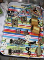
old preamp:
I have a regular 5842 => IT => 300B and it is time to make it better. I don't open a new thread because 45 or 300b is about the same challenge.
I know that the best operating point of the 5842 is B+ 150 volt and about 12 mA 😎
I also have a 5842 => lundahl LL1630 preamp (same topology as frontend of poweramp), so I first will use this as a guinea pig.
The thing I changed is that I used a 10M45S chip between B+ and the LL1630 and I took 1 choke/channel out of the preamp. PSU is now 0,1 uF => shared choke 10H =>47 uF => 430R => 47 uF.
I still have tot try a 0A2 regulator (150 volt) after the chip. But first I tried a 25 uF motorruncap between cathode and B+ (at that time there was a 180 ohm cathoderesistor without bypass of capacitor). That gave a great amount of (50Hz I suppose) hum. In fact I took the setup from Davitsk: http://www.ecp.cc/SSS.html
Question is, how is this possible ? I have two 100R carbon resistors parallel between hot side of the 100K pot and the two groups of gridpins on the 5842.
To get rid of the hum I took the 180R cathoderesistor out and changed it for a reddish LED. This gave 1,8 volt on the cathode and about 136 volt B+ if I remember well. The 25 uF motorruncap is now parallel on the 10M45S and not on the cathode anymore.
Hum is now tolerable and the sound of the preamp is much much better, I might say shocking better than in the old topology (cathode resistor bypassed with 220 uF cerafine and PSU with shared choke and after that CLC for each channel).
Things that come to my mind to get the hum more down:
* more capacitance
* lift the ac filaments with x volt
* dc on filament
Any advice ?
By the way, did you realize that you should not touch the small (isolated) bolt with which the 10M45S is tied to the chassis when the amp is on ? I did, a few seconds ago
old preamp:
Attachments
Hi!
At 45 tube is not so simple and cheaper amp. If a reasonable estimate, and to expend efforts and resources)
This is your first amp?
Then do not start with such a sophisticated sounding tube. It is unlikely that, without much practical experience you will get a positive result. All the more so that the tube needs very transparent sounding acoustics. High-quality transformers, and so on.
That such a scheme. Or any close to it.
With vacuum-tube SE a sound. I.e. with a good vacuum-tube sound. Four vacuum-tube watts with transformers Edcor/Hammond will well shake acoustics> 90 dB/m. You will get pleasure from the sound, and the DIY process.
Input tube it 6SJ7. The second tube it 6L6. The rectifier 5U4G.
BW,VU
At 45 tube is not so simple and cheaper amp. If a reasonable estimate, and to expend efforts and resources)
This is your first amp?
Then do not start with such a sophisticated sounding tube. It is unlikely that, without much practical experience you will get a positive result. All the more so that the tube needs very transparent sounding acoustics. High-quality transformers, and so on.
That such a scheme. Or any close to it.
An externally hosted image should be here but it was not working when we last tested it.
With vacuum-tube SE a sound. I.e. with a good vacuum-tube sound. Four vacuum-tube watts with transformers Edcor/Hammond will well shake acoustics> 90 dB/m. You will get pleasure from the sound, and the DIY process.
Input tube it 6SJ7. The second tube it 6L6. The rectifier 5U4G.
BW,VU
Yes
I agree that for a first amp you better can try a cheaper tube than 300B/45 and I also agree that you should go PP if you do not have sensitive speakers.
For a first amp a ECL86 or ECL82 PP amp would be a good choice.
But that is not the question. I already have a IT coupled 300B amp that is not bad but perhaps could be bettered.
I am experimenting with 10M45S on top of interstage (or better, I try it first on preamp with LL1630 OPT). I would like to get rid of the cathode capacitor and have some trouble with the WE style capacitor from cathode to B+ (hummmmm).
Just revisitin this design, I have completed a Decware SE84 kit since now, and consider this design to be something a little more than a 'first amp'.
I am now experimenting with different driver stages, and different methods of coupling. My current thoughts are interstage transformer, and with regards to the driver: 26, D3a, 5842/417a, C3g and C3m. With these tubes, would it be possible use still a CCS to feed the plate?
I presume my previous presumptions regarding the 45 is still valid, as I'd like to keep that. My PSU at this time is: 50R/4uF/15H(CM Choke)/50uF/20H(1 for each channel)/50uF. Perhaps a little over done, but I have all the parts.
dsavitsk said:The 5842 works well with LED bias. With a 20mA CCS and a red led (1.8~2V), you'll end up w/ about 160V on the plate which I have found to be a good spot. Also, try the 6688 triode strapped -- electrically very similar, sounds at least as good, and costs less.
Doug,
Have you tried the E180F (6688 equivalent) also?
TIA,
- Status
- Not open for further replies.
- Home
- Amplifiers
- Tubes / Valves
- Simple 5842-45 SET Amp Design Idea