It depends on the tube, on its operating point, on the stage topology and on where you want the UHF rolloff frequency to be.
What is Miller Capacitance?
Is miller Capacitance relevant at audio frequencies? I have too look at that thanks. That is not an easy topic.
It might be relevant if the previous stage output impedance is too high. It is often deliberately used in the guitar amps.Is miller Capacitance relevant at audio frequencies?
But with the grid stoppers you basically want to create the low-pass RC filter out of the grid stopper itself and the Miller "capacitor" with the cutoff frequency somewhere above the audio region but below the "problematic" (prone to oscillation) HF region (some MHz).
If the grid leak and the tube grid to plate capacitance forms the RC filter, what is going on with the impedance from the previous stage? How does that effect it?
When a tube is amplifying a signal, it has to work against the plate-to-grid capacitance, charging and discharging it as the signal changes. Because the grid is a high impedance, and doesn't sink or source any current, this charging current must be sourced or sinked through the driving source resistance of the previous stage. This forms a lowpass filter, with a corner frequency determined by the source resistance of the previous stage and the input capacitance.
Could you explain that a little better in respect to the grid stopper it sounds like it would be better not to have one in the case of a high impedance previous stage?
Could you explain that a little better in respect to the grid stopper it sounds like it would be better not to have one in the case of a high impedance previous stage?
Audiowize
Excellent explanation/tutorial. You made it simple.
I saved your posts and images to a word doc for future reference.
Steve
+1
This is a really helpful snout-to-tail walkthrough of the basics.
Request @ audiowize: can you please repost the image in post #26? I am unable to see or open it in either Chrome or Opera.
cheers and many thanks, Derek
An externally hosted image should be here but it was not working when we last tested it.
We will borrow from another similar design to illustrate where things go.
The 33K/2W plate load in this schematic would be your 22K resistor. 8mA goes through it, so P=(I^2)*R, so dissipated power is 1.4W, so I would make it a 5W resistor so it lasts. You may need to look at values between 20K and 25K. This is OK. You aren't building a spacecraft.
The 2.2K cathode resistor on the first stage we have calculated to be 250 ohms. You don't need the bypass cap.
For the cathode follower section, we know the voltage at the grid will be about 145V from the previous stage, and the cathode will be just slightly above that, call it 150V. If you use a 22K resistor from cathode to ground, that'll get you 7mA of cathode current, which is fine. This goes in place of the 24K/3W part in the drawing.
Here is an upload of the image. It's the old JE labs 76/6SN7 preamp. I should also mention that these aren't the values I would use, but they are a valid start.
Attachments
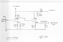
It's the old JE labs 76/6SN7 preamp. I should also mention that these aren't the values I would use, but they are a valid start.
What would you change, and why? The reason I ask is a friend build this stage years ago with 6SN7's, and used those exact values for load and cathode resistors. IIRC the preamp sounded ok.
jeff
Relying on the pot itself when providing the 0V reference to the grid is very bad practice. Pots fail. Even the best ones. In fact, they "micro-fail" tens or hundreds of times every time you adjust the volume.
I don't think it is a horrible practice. Plenty of amps are built like that and work just fine.
However I also agree that it is a decent idea to add a second resistor for some added insurance. Especially if you are using some unobtanium preamp tube like an EC8020 or something like that.
We should distinguish between filtering the audio signal (which you might or might not want depending on the design goals) and reducing the electromagnetically induced UHF components (which you always want since they are the primary reason for UHF oscillation).Could you explain that a little better in respect to the grid stopper it sounds like it would be better not to have one in the case of a high impedance previous stage?
In the first case the output impedance of the previous stage should be taken into consideration when calculating the useful bandwidth. In the second case it doesn't really matter (and should be omitted from the calculations) because you are trying to deal with something that appears directly at the stage input.
And that's why grid stoppers should be placed as close to the grid pin as possible - moving them physically back to the previous stage just raises this stage output impedance and doesn't really stops anything.
Hi all,
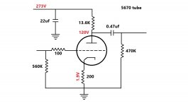
Following some of the guide lines I've assembled the circuit as in the attached drawing and it's working(thanks guys).....there is only one issue, it appear that my DAC output is over loading the tube so I'm getting some distorted sound, lowering the DAC output using it's built in digital volume solve the problem but I don't want to use the digital volume to reduce it's output so I would like to know reason and how to solve this issue.
I'll appreciate your comments/suggestions.
Attachments
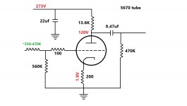
The exact resistor value depends on the DAC max output:and how to solve this issue.
Attachments
What would you change, and why? The reason I ask is a friend build this stage years ago with 6SN7's, and used those exact values for load and cathode resistors. IIRC the preamp sounded ok.
I was referring to the really generic values I cooked up for a 5670, I didn't do any analysis on the other design, and I would expect it to be a little better developed than what I presented here.
A common DAC often has about 2.1VRMS full scale output (3V peak).
Directly connecting the DAC output to the grid of a preamp that only has 1.9V bias will have very bad clipping (any signal over 1.9V will draw grid current).
And a 5670 tube has a u of 35; a transconductance, gm, of 5500 micro Mhos; and a plate resistance, rp, of 6,363 Ohms. Your plate load, RL, is only 13.6k. That is only about 2 times the tube plate resistance. Using an RL that is only 2 times rp, is a bad prescription, it will have lots of distortion.
With an RL that is 2 times rp, the gain is 2/3 x u = 23.3.
Even if you use a resistive attenuator between the DAC output and the preamp input, you will still have the distortion issue caused by the RL versus rp ratio.
All that sounds pretty much like the performance you got.
Last edited:
Try 6k8 as anode resistance.Gives a more negative grid and less gain.Hi all,
Following some of the guide lines I've assembled the circuit as in the attached drawing and it's working(thanks guys).....there is only one issue, it appear that my DAC output is over loading the tube so I'm getting some distorted sound, lowering the DAC output using it's built in digital volume solve the problem but I don't want to use the digital volume to reduce it's output so I would like to know reason and how to solve this issue.
I'll appreciate your comments/suggestions.
Mona
Try 6k8 as anode resistance.Gives a more negative grid and less gain.
Mona
By anode resistance do you mean the Rp?
6K8 reistor is almost the same as the 5670 tube plate resistance of 6.4 Kohm.
To replace the 13k6.By anode resistance do you mean the Rp?
6K8 reistor is almost the same as the 5670 tube plate resistance of 6.4 Kohm.
Mona
- Home
- Amplifiers
- Tubes / Valves
- Simple 5670 tube based line stage design help