This will be simple for anyone that knows simple stuff really
Have a pc power supply that's got a 12v regulated output that I want to put into an lm217t to get an adjustable output. I have a B1k variable resistor to hand so would prefer to use that to get it to work and want as close as possible to 0v-12v variable output
Who can help...
Please post a simple schematic
You will not get the full 12V output using the LM317 family of adjustable regulators when the supply is only 12V.
There will be some drop across the regulator that will vary with current drawn.
Review the data sheet for the actual (expected) drop vs current.
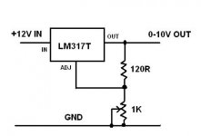
see jpg for typical application.
(capacitors for stability not shown)
There will be some drop across the regulator that will vary with current drawn.
Review the data sheet for the actual (expected) drop vs current.
see jpg for typical application.
(capacitors for stability not shown)
Attachments
You will not get the full 12V output using the LM317 family of adjustable regulators when the supply is only 12V.
There will be some drop across the regulator that will vary with current drawn.
Review the data sheet for the actual (expected) drop vs current.
see jpg for typical application.
(capacitors for stability not shown)
Yeh I know I won't get the full 12v and that's fine just wanted the best optimization for this little circuit as possible
How many amps does the lm217t supply?
What caps would you recommend? Or do I not need them as it is a fully regulated power supply...
Your question begs for a long answer to be complete.
Current depends on drop across and temperature of the regulator. No simple answer.
Check the data sheet: http://www.onsemi.com/pub_link/Collateral/LM317-D.PDF
Learn well.
Current depends on drop across and temperature of the regulator. No simple answer.
Check the data sheet: http://www.onsemi.com/pub_link/Collateral/LM317-D.PDF
Learn well.
Yes you can use your 1kVR to control the output voltage of your supply.
The range of adjustment for a 12Vdc input will be ~ 1.25Vdc to 10Vdc.
The dissipation when set to low voltage will severely limit the output current.
There are other Threads showing better ways to do this.
I mention what I have done.
2.75A (secondhand Ebay) Variac feeding a 100VA 25+25Vac transformer. Output is variable from 0+0Vac to 25+25Vac. This is fitted into the box holding my bulb tester and my mains output from the same Variac.
Two pair of 4mm banana sockets feed that variable AC into a pair of PSUs to give me +-0Vdc to +-35Vdc @ ~1Adc continuous and many Apk to power most of what I build.
I also have an Ebay second hand dual output Lab supply that does 0 to 30Vdc @ <=3.1Adc continuous, twice over, with variable current limiters and ability to parallel or series connect the two independent outputs.
Last edited:
Ok so I got it all together and it works but I only get voltage control on the first quarter turn of the knob, so it goes from around 1.4 to 11v just in the first quarter turn
How can I get full adjustment across the whole knob? I really need it this way to get more accurate control...
Thanks in advance
How can I get full adjustment across the whole knob? I really need it this way to get more accurate control...
Thanks in advance
Is the pot logarithmic or linear?
LM317 needs around 3V minimum Vin-Vout difference to work well and it can provide a max current of 2A between 5 to 11V dropout.
LM317 needs around 3V minimum Vin-Vout difference to work well and it can provide a max current of 2A between 5 to 11V dropout.
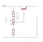
If the 12 volt supply is regulated, u need not go for an LM317. Just construct a variable voltage circuit using single transistor and couple of parts. Added advantage is that u will get a bigger span than the LM317.
Gajanan Phadte
Gajanan Phadte
Hi,
You need to increase the variable resistor about 2K. Or add a 200 ohms resistor in series with the Ik. Also your input voltage need to be higher that 12 volts. Possible about 15 volts.
You need to increase the variable resistor about 2K. Or add a 200 ohms resistor in series with the Ik. Also your input voltage need to be higher that 12 volts. Possible about 15 volts.
The circuit is like this.
Change the transistor according to the load current required. May be heatsinked also.
Add a small capacitor(optional) from base to negative.
Gajanan Phadte
Change the transistor according to the load current required. May be heatsinked also.
Add a small capacitor(optional) from base to negative.
Gajanan Phadte
Attachments
Last edited:
Scale the transistor for the current required and add a capacitor(optional) from base to negative.
I just came across this circuit here (scroll down to Simple Adjustable Voltage Source):
Telephone In-Use Relay, LM317 Regulators, Lithium Charger
And this sounds perfect
Now my questions are, how many amps could this simple npn pnp circuit provide? Also just how much heat will it produce?
I only have the small clip on heatsinks that I can put on it although I could possible place it on the larger heatsink in the power supply and possibly even next to the slow running 80mm intake fan if needed?
I think I will go this route as it's simple and cheap just need to know how many amps I can get in this circuit and how well I need to cool it
If possible I would like to be able to supply up to 5a so if different parts are needed in this same circuit please do let me know although I could live with 2a output
Power dissipation across the MJE2955 should not exceed its rating. Not exceeding the junction temperature of the device is important.
Gajanan Phadte
Gajanan Phadte
I never use theese so called voltage regulators, they have no tollerance what so ever to the variations of the imput voltage cus they have no stable Vreff, so any change in the voltage at it's imput translates in a similar change at the output, that is no regulator, just a worthless follower.
The simplest way you can get a voltage regulator is with LM317 but it needs that minimum voltage difference to work, another way would be with a fixed Vref, let say a 5,1V zenner and an error amplifier, transistor differencial or OA, they have the advantage of less voltage drop across them and a verry fine voltage setting but they are sort of more complex. If you are interested i can provide a schematic that u can use.
The simplest way you can get a voltage regulator is with LM317 but it needs that minimum voltage difference to work, another way would be with a fixed Vref, let say a 5,1V zenner and an error amplifier, transistor differencial or OA, they have the advantage of less voltage drop across them and a verry fine voltage setting but they are sort of more complex. If you are interested i can provide a schematic that u can use.
I never use theese so called voltage regulators, they have no tollerance what so ever to the variations of the imput voltage cus they have no stable Vreff, so any change in the voltage at it's imput translates in a similar change at the output, that is no regulator, just a worthless follower.
The simplest way you can get a voltage regulator is with LM317 but it needs that minimum voltage difference to work, another way would be with a fixed Vref, let say a 5,1V zenner and an error amplifier, transistor differencial or OA, they have the advantage of less voltage drop across them and a verry fine voltage setting but they are sort of more complex. If you are interested i can provide a schematic that u can use.
As ive said before my input is from a pc power supply's 12v so the 12v is extremely regulated already and shouldn't fluctuate at all unless I put maybe 30A on it, using a simple circuit and only pulling 5a it shouldn't fluctuate, maybe .1 of a volt max
I will go with the simple circuit I posted above and will share my results when its all up and running
As ive said before my input is from a pc power supply's 12v so the 12v is extremely regulated...
Actually the outputs of a ATX power supply are well regulated only when they are equally charged, that is the 2 main outputs, +5 and +12V, they both need the same load current for theyr voltages to be stable. You cand try it yourself, charge the 5v with 5 amps and 12V with 1 amp, you will see what i mean.
I never use theese so called voltage regulators, they have no tollerance what so ever to the variations of the imput voltage cus they have no stable Vreff, so any change in the voltage at it's imput translates in a similar change at the output, that is no regulator, just a worthless follower.
The simplest way you can get a voltage regulator is with LM317 but it needs that minimum voltage difference to work, another way would be with a fixed Vref, let say a 5,1V zenner and an error amplifier, transistor differencial or OA, they have the advantage of less voltage drop across them and a verry fine voltage setting but they are sort of more complex. If you are interested i can provide a schematic that u can use.
U have to read the posts properly. They r not voltage regulators at all. It is a voltage varying circuit connected to a regulated supply.
Enjoy
Gajanan Phadte
U have to read the posts properly...
Do i? i sayd so called voltage regulators, ofcourse i know what they are, and getting stuck on sematics helps nowone, from my point of view they remain simple followers, worthless in voltage regulation/setting/variating, or anything else you wanna call it. And as i sayd the outputs on a ATX supply is only well regulated on some conditions so i would not use this for anything, there are other ways much more stable and efficient.
- Status
- Not open for further replies.
- Home
- Amplifiers
- Power Supplies
- Simple 12v adjustable help