I was looking to replace the three filter capacitors in my Silvertone amp. The amp originally came with a can capacitor with a 5-, 10- and 20-micro farad capacitors. I was wondering if anyone had photos to share that shows where you relocated the new caps in the chassis. I installed a three lug terminal strip that grounds to one of the transformer mounting bolts.
The 10-micro farad, orange wire, connects to pin 4 of one of the 6V6's and could be easily run to the new terminal strip. The 5-micro farad , red wire, runs to an original terminal block near the other 6V6 and the one of the 12AX7's. I could possibly utilize the new terminal strip for that ground. The 20-micro farad has two red wires, one runs to the output transformer and the other goes to pin 9 of the rectifier. The chassis has room near the tone and volume controls for the microphone and instruments where I could possibly put a terminal strip. By putting the new caps in that area, will I be generate any additional unwanted noise?
The 10-micro farad, orange wire, connects to pin 4 of one of the 6V6's and could be easily run to the new terminal strip. The 5-micro farad , red wire, runs to an original terminal block near the other 6V6 and the one of the 12AX7's. I could possibly utilize the new terminal strip for that ground. The 20-micro farad has two red wires, one runs to the output transformer and the other goes to pin 9 of the rectifier. The chassis has room near the tone and volume controls for the microphone and instruments where I could possibly put a terminal strip. By putting the new caps in that area, will I be generate any additional unwanted noise?
So others may play along at home, here is the schematic:
http://bmamps.com/Schematics/Silvertone/silvertone1482.pdf
This is a guitar amp, so the thread belongs down in the instrument amp section.
http://bmamps.com/Schematics/Silvertone/silvertone1482.pdf
This is a guitar amp, so the thread belongs down in the instrument amp section.
As the design uses a single point common ground for the capacitor, I would excavate the old capacitor and put a 22uF 450V cap inside and the other two should come from the 22uF ground point. Maybe there will be enough room for an extra cap in the old case?
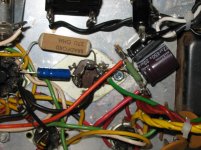
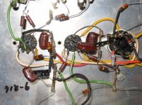
I mounted a 22uF and 10uF cap for the B+ and screen supply on a 3 lug, center ground terminal strip, and put a 2.2k resistor between them. Drilled out one of the rivets on the old can cap and mounted the terminal strip there. The old can cap's positive terminals were wired together and connected to the ground lug of the new terminal strip, and this was used as a local ground bus for the output stage, including a new cathode bypass cap.
The R & C for the 12ax7's supply were placed near those stages using existing connection points. The 27k is the gray resistor from the octal socket to the nearby terminal strip, and a 10uF connected to the terminal strips between the two preamp tubes, with heat shrink insulating the positive lead.
The R & C for the 12ax7's supply were placed near those stages using existing connection points. The 27k is the gray resistor from the octal socket to the nearby terminal strip, and a 10uF connected to the terminal strips between the two preamp tubes, with heat shrink insulating the positive lead.
Attachments
Hi there , you could just replace the can this ones close
https://www.tubesandmore.com/products/C-EC2010X2-475
https://www.tubesandmore.com/products/C-EC2010X2-475
jgf - Thanks for the photos, they are very helpful. It looks like radial style capacitors work better in this instance than axial type..
jonsnell - Is it important to ground all the filter caps in the same location?
jonsnell - Is it important to ground all the filter caps in the same location?
jgf - Thanks for the photos, they are very helpful. It looks like radial style capacitors work better in this instance than axial type..
mike60510 - You're welcome. The choice of caps was driven both by fit on the terminal strips, and by cheepnis.... an important trait in this amp. An axial cap of modern proportions could probably fit on the preamp terminal strips.
- Status
- Not open for further replies.
- Home
- Live Sound
- Instruments and Amps
- Silvertone 1482 Capacitor replacement

