i just had a brainfart while rewinding an OPT...
ok, standard push pull has the primaries connected in series at the CT, as we all should (hopefully) know. obviously in phase as well. then we drive the tubes with a 180 degree out of phase signal. yay. thats normal.
but i just had a thought... what if i wired my primaries in series...out of phase, then didnt bother with the phase inverter at all? so both tubes are in phase?
any thoughts? yes, i know...probably only going to work in pure class A...
i might have to experiment with this idea at some stage!
just, um...not right now.
ahhh, the strange ideas people get at times 🙂
but i just had a thought... what if i wired my primaries in series...out of phase, then didnt bother with the phase inverter at all? so both tubes are in phase?
#1 is the usual PP connection. For Class A PP, this is a balanced, two-phase system that works as you'd expect. Phase voltages add (by KVL) and there is no differential current in the common (which is the case for all balanced polyphase connections). DC in the neutral will result in differential magnetization, and therefore cancellation of DC magnetization, and no need for an air gap to prevent saturation.
#2 will yield no output voltage, as the phase voltages cancel. If that side is driven with voltages of equal magnitude in phase, you have essentially a single-ended parallel connection. Any DC in the common will cause cumulative magnetic fields, and as for any other single-ended connection, you'll have a DC mag problem that will be needing an air gap in the core.
It's been done before.
Attachments
Last edited:
This reminds me of a paper from the GenRad Experimenter 1951. Not the same as the OP's idea but also a different way to connect both halves of the OPT.
Skip page 1 and Fig.1 for the moment and have a look at Fig.2 on page 2: https://www.ietlabs.com/pdf/GR_Experimenters/1951/GenRad_Experimenter_Oct_1951.pdf
The authors claim: quote: In the usual push-pull circuit the two output tubes are in parallel for the dc plate supply and operate effectively in series for supplying the AC load. In a limited sense this new circuit can be considered the opposite of the usual circuit since the output tubes are in series for the dc plate supply, and they supply the ac load in parallel ... If the two halves of the primary are separate, they can be connected in parallel, instead of in the series connection ordinarily used... Because of this parallel or single ended connection of the primary, both tubes work into the same load, and there is no deleterious effect from leakage reactance between halves of the primary.... unquote:
pretty well much as i thought after posting this. its just going to be a parallel system but with the anodes at opposite ends of the tranny... so the air gap would be necessary. just interesting to see other (more knowledgable) peoples opinions...
This reminds me of a paper from the GenRad Experimenter 1951.
Not the same as the OP's idea but also a different way to connect both halves of the OPT.
Skip page 1 and Fig.1 for the moment and have a look at Fig.2 on page 2:
https://www.ietlabs.com/pdf/GR_Experimenters/1951/GenRad_Experimenter_Oct_1951.pdf
The basic schematic (Fig 1.) in the Gen_Rad article is essentially like a totem-pole OTL, which is then used to drive an output transformer, rather than having the speaker itself form the load.
Originally Posted by Sorento This reminds me of a paper from the GenRad Experimenter 1951. Not the same as the OP's idea but also a different way to connect both halves of the OPT.
Skip page 1 and Fig.1 for the moment ...
A little late for a reply, but anyway ...
That is why I said not to look at Fig.1 which is just to make a point for the patent. However in Fig.8 they show how they actually designed their amp.
The OPT's primary is split in 2 halfes. The upper output tube only works into the lower half of the OPT while the lower output only works into the upper half. The electrolytic shown between both outputs is not a coupling cap for the OPT. Both half primaries are directly connected to their respective tube and DC cancels.
It works quite well in spice, PSR however is horrible ... probably requires a regulator.
Skip page 1 and Fig.1 for the moment ...
The basic schematic (Fig 1.) in the Gen_Rad article is essentially like a totem-pole OTL, which is then used to drive an output transformer, rather than having the speaker itself form the load.
A little late for a reply, but anyway ...
That is why I said not to look at Fig.1 which is just to make a point for the patent. However in Fig.8 they show how they actually designed their amp.
The OPT's primary is split in 2 halfes. The upper output tube only works into the lower half of the OPT while the lower output only works into the upper half. The electrolytic shown between both outputs is not a coupling cap for the OPT. Both half primaries are directly connected to their respective tube and DC cancels.
It works quite well in spice, PSR however is horrible ... probably requires a regulator.
Last edited:
The basic schematic (Fig 1.) in the Gen_Rad article is essentially like a totem-pole OTL, which is then used to drive an output transformer, rather than having the speaker itself form the load.
Not so, not so ... in Fig.8 they show how they actually designed their amp.
The OPT's primary is split in 2 halfes. The upper output tube only works into the lower half of the OPT while the lower output only works into the upper half. The electrolytic shown between both outputs is not a coupling cap for the OPT. Both half primaries are directly connected to their respective tube and DC cancels. AC wise however both halves of the OPT work in parallel, both single ended.
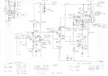
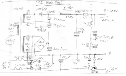
Of course I prototyped this as well, took me a while though ...
Tubes are 1xPCF80 and 2xPL36 per channel.
OPT is a cheap Indel SE which happens to have a CT brought out. The primary is cut at the CT and is now split into two parallel primaries.
Attachments
- Home
- Amplifiers
- Tubes / Valves
- silly ponderings on OPTs and phase inversion.