Hi, were you able to sort this issue and get better measurements?My DSC2 measurements
I took some time to make measurements of my DSC2 build (shown at https://www.diyaudio.com/forums/digital-line-level/254935-signalyst-dsc1-141.html#post5830294) before starting case construction. My results do not seem to be in-line with the measurements others are seeing. I'm wondering where I may have gone wrong and if there are any suggestions to get my THD measurements up to par with what other are seeing (https://www.diyaudio.com/forums/digital-line-level/254935-signalyst-dsc1-151.html#post5890188, etc).
While the measurements others have posted are around 0.007% THD, I am consistently seeing 0.013% in one channel, 0.017% on the other. I have attached my RTA spectrums.
Tests were run using a 1khz sine 384k/24bit wav file generated with SoX, -3db attenuation. This is upsampled to DSD512 or 256 in Roon (no meaningful differences in THD between the rates). Balanced output sends about 1.22V output to my Linear Audio Autoranger (which leaves attenuation to 0db) and then to my ESI Juli@'s balanced inputs.
Any thoughts on the cause of this? I have tried a few things to rule out some thoughts.
- Changed from a switch mode PSU with a cap-mx + regulator to a linear PSU + cap-mx + regulator. No changes in THD.
- Tried both SE and Balanced outputs, no change
- Tried HQPlayer instead of Roon for upsampling, no change
- Added 10k across the secondary of the output transformer (Lundahl LL1684), no change
Some suspicions I have:
- I ordered some 74AHCT595Ds from Taobao in an attempted to get old stock. It seems like they were based on NXP marking, but I wonder now if they are legit parts.
- It was stated by Vit123 that the Lundahls add significant distortion, but even for these transformers, is it expected to be this high?
- Any grounding issues? Right now its pretty isolated from anything, but I suspect this wouldn't be that big of an issue with balanced output. I also would assume any grounding issue wouldn't be spread across the harmonics as I'm seeing.
- Soldering or construction errors? Anywhere to start to check this? I read the previous posts about DC across the transformer primary. I measured and there is no substantial or constant DC voltage while playing music.
- Should I add additional snubbing or load to my output with the LL1684s?
- Perhaps my test setup is flawed.
Or... maybe these measurements are as expected with my build?
Any suggestions on where I can go next to try to lower the THD? Any other tests I should be running? Any other information that would be helpful?
Thanks all for your thoughts and expertise!
Greg
Can you share them
He could try with a slightly lower level signal (-4,-5 or -6 dB), instead of -3dB.
Wonder what that does.
Wonder what that does.

Is Pavel still active?Hi @ppy
Jussi (HQP) has mentioned:
Can you share details about what has been implemented in your DSC2 design?
An improvement over DSC1 ?
Thanks!
Can anyone share any info about this comment by Jussi (HQPlayer) and if it is implemented in DSC2 design ?
"make and model of the switch register-latches is pretty critical. Even if the model number is the same, different manufacturers have different implementations. Although they all work the same from digital data function point of view. However, this DAC use is a mixed-domain use case and very different from what the chip was originally designed for."
Or is Pavel the only one that can answer this?
Iirc Pavel stated he used HQPlayer with the AMDSM modulator for best results.
Did you use HQPlayer and at what level did you set it to?
Did you use HQPlayer and at what level did you set it to?
I'm busy with a friend to revive this project. We made some modifications, as we do not feel the need for an active output.I decided to stop working on the DSC2 project.
The development of the latest version of DSC2 is completed. But not yet implemented as real PCBs. I hope someone can bring this version to its logical end.
I offer a complete set of project files in the KCad format - http://puredsd.ru/dsc2expra_rel.zip.
The project documentation and source code is published on an “as is”.
The project consists of two parts:
Thanks to Jussi, as the author and everyone who helped to develop this project.
- main - main PCB DSC2 with transformer output and Open Hardware License. Interactive BOM for KiCAD
- output_nazar - active output PCB for replacing transformers. Circuit decisions are taken from open sources. But do not support Open Hardware License Interactive BOM for KiCAD
Attachments
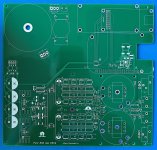
Yes that is looking verry good.
We have updated this project together and i am verry curios to see the bords in real live.
Here is a list of the changes we have made to the project.

We have updated this project together and i am verry curios to see the bords in real live.
Here is a list of the changes we have made to the project.
- We have removed the power supply for the Nazar.
- The clocks have been replaced for Crystek clocks.
- Removed the ground plane under the condensor row.
- Rearranged the annotation of all components on the board.
- Added space for an additional PSU for the USB interface.
- Added an extra center pin on the output transformer to make the yellow Ali transformers fit.
- Removed the inverter U36
- Added the missing 3D components.
HII'm busy with a friend to revive this project. We made some modifications, as we do not feel the need for an active output.
Is PCB tested ?
While the PSB batch hasn't gone into production yet, a significant improvement in mute performance can be made. It is necessary to give a mute signal to 15 pin registers. And to refuse analog keys on an output. This method implements soft mute.Yes that is looking verry good.
We have updated this project together and i am verry curios to see the bords in real live.
Here is a list of the changes we have made to the project.
- We have removed the power supply for the Nazar.
- The clocks have been replaced for Crystek clocks.
- Removed the ground plane under the condensor row.
- Rearranged the annotation of all components on the board.
- Added space for an additional PSU for the USB interface.
- Added an extra center pin on the output transformer to make the yellow Ali transformers fit.
- Removed the inverter U36
- Added the missing 3D components.
We are doing that by reviving the project, so no, not yet.HI
Is PCB tested ?
Yes, probably very good tip, the timing is a bit of for us, we now already have the PCB. Maybe indeed for the next batch.While the PSB batch hasn't gone into production yet, a significant improvement in mute performance can be made. It is necessary to give a mute signal to 15 pin registers. And to refuse analog keys on an output. This method implements soft mute.
There is an alternative PCM->DSD256 converter project in the forum which IMHO is likely to sound better than DSD'it. No offense intended to Pavel by saying that either. Using dual AK4137 ICs was definitely one of the good things to try. The other converter project guys used an FPGA for synchronous conversion instead of AK4137. IMHO the synchronous converter has some significant advantages. BTW, like Pavel I made my own dual AK4137 design too; so I tried the same idea as Pavel, but in a bit more involved and costly type of way. The FPGA guys figured out a better way yet, is all. So now I use their version. While it is better than AK4137 for various reasons, it still isn't quite at the level of what is possible with HQ Player, nor maybe quite as good in some ways as the freeware offline converter at: https://pcmdsd.com/Software/PCM-DSD_Converter_en.html FPGA converter is still better than AK4137 though (not that AK4137 is bad, its just asynchronous which brings some complications along with it).is it possible to use DSD'it?
The above having been said, I believe the guys behind the FPGA-based Simple DSD Converter project are thinking about ways to improve the firmware algorithm. Have listened to some beta level ideas. Not too bad. Even as it is now, IME its probably the best sounding hardware DSD converter diy project available at the moment.
If there happens to be any interest the FPGA-based project, thread is at: https://www.diyaudio.com/community/threads/simple-dsd-modulator-for-dsc2.370177/
Last edited:
@jeroen_d I'm really interested in your project, are you going to build a working prototype of this board?We are doing that by reviving the project, so no, not yet.
Thank you and regards,
Gaetano.
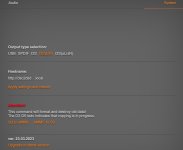
The board is playing through the beaglebone network option. The sound is very, very good. Most of the difference is in the midrange, very full and warm. With the V2.6.2 the optimal rate was DSD256, DSD512 gave less space and a bit fuzzy treble. Now when I use DSD512 it becomes even better. DSD256 is already very good with ASDM7ECv3. Beautiful and fluent. With DSD512 I prefer ASDM7EC-super 512+fs, very dynamic.
The USB option however, I cannot get to work properly. I get only very distorted sound. The selectorchip for Amanero vs BBG seems to work properly so I do not know what the problem is.
The USB option however, I cannot get to work properly. I get only very distorted sound. The selectorchip for Amanero vs BBG seems to work properly so I do not know what the problem is.
Then the mute funtion. It is hopeless. Reading the instructions, J9/P28 should be a better option. Well, not. It is just doing nothing. It is clear that pure/botic is ignoring this pin. So back to P27, which is functioning, but far from perfect. Without the resistor 4k7 pulling it to 3,3V it only functions well when the BBG has fully started. If you do not wait with turning on your amp, a nasty noise pulse is audible. So resistor 4k7 is needed for a safe start up with the amplifier on. No nasty noises at all. But then the problem is that it stays high with no music all the time. And the first track you play, no matter 44.1 of 48 family, also gives a pop. And then mute stays always on so you cannot use the Amanero. Without the 4k7 resistor and powering the amp on only after startup, you can safely start with the 44.1 family.
This means that I am now leaning towards not using the Amanero option at all. I'm completely satisfied with the sound, cannot imagine a DAC sounding better.
Then a last annoyance with the mute remains: loud pops when swithing clock rate. It seems that the timing is off and that the mute should be activated a bit later. I have read the botic support topic and tried to increase in uEnv.txt the mute delay but this does not seem to have any effect. The botic driver does not seem to react on the mute delay spec at all. Removing the spec of 500ms delay does not make a difference. If I let HQPlayer not use the 48 family, I can play safely without pops.
Last edited:
Use the instructions from my page https://puredsd.ru to switch Amanero to slave mode. You can also get the "Pure" firmware for BeagleBone there. There's a modified botic with normal mute work.
- Home
- Source & Line
- Digital Line Level
- Signalyst DSC1