Wouldn't a capacitor fastener for holding the base, and wires soldered to the pins be easier? I'll experiment later!
Good call - didn't think of that.
All other creative ideas welcome! Let's solve the socket problem.
This will be my solution, but I am awy from home and only have octal bases with loctal adaptors, so cannot show it exactly.
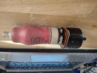
The CT base comfortably fits into the base, so I will solder wires to the interesting pins, and feed them through the octal pins and solder them. (Like I did with the wafer loctal base). Then if need be I will add a heat resistant mastic to the gap between the bases so I can treat the tube as an octal without worrying about handling.
Most CT tubes were just alternative bases of standard tubes, so if it is wired in the correct way for the octal base, it is just converting from one tube to its equivalent.
The loctal adaptors I created have the wafer base attached with epoxy resin, and apart from one poorly soldered octal pin, they have worked very well. Here that are with 5B/255M tubes on a Quad II.
Sorry about the inverted images! Looked fine on the PC.
Attachments

Last edited:
Well... I might not be on the same side here.
Yes, the newly designed P-socket remakes are awfully and made from the wrong materials which will destroy (older) tubes.
Score some older ones, take them apart, clean thoroughly, give the metal contacts their curve again and you will have a quality socket that clamps the tube just enough and holds contact perfectly.
I have been using these sockets for years and years now without any problem, from powertube up to first stage of my riaa-correction amplifier(s). That is the CF50 set at a gain of almost 300. Not a hiss, crackle, nothing..
Read on, use translation if you like, taken from Rohren 1934 in Europa, Teil I, A- C- und E- Serien
For short: Socket was designed for low height applications, offered a solution for AC-heating and electrodes to tube connection is almost capacity free.
Further on, and that is my opinion 🙂 , these sockets have a better influence on sound than the bigger contact sockets like octal, and UX-varieties..
But again, use old stock, clean and restore!
---
Die neuen Sockel der Gleichstrom-Wechselstromröhren
Um die Vorteile der kleinen Abmessungen der Philips G/W-Röhren voll ausnützen zu können, haben die Philips Laboratorien einen neuen Sockel entworfen, welcher von den bisher verwendeten Sockelausführungen grundsätzlich abweicht und sich durch so wesentliche Vorteile auszeichnet, dass dieser endgültig für die neuen G/W und Autoradio-Röhren verwendet wird. Diesen Sockel hat Philips mit P- und V-Sockel bezeichnet. Abbildung 1 zeigt eine neue Röhre mit dem P-Sockel und der neuen Röhrenfassung. Der P-Sockel ist mit 8 Elektrodenanschlüssen ausgeführt, während der V-Sockel mit 5 Elektroden ausgeführt worden ist. Der V-Sockel ist nur für die Doppeldiode CB1 entworfen.
...
Der Hauptvorteil dieser neuen Sockel besteht in den kleinen Abmessungen. Wenn beispielsweise die totale Sockellänge, also mit Stiften, der bisherigen Ausführung der Hochfrequenzpenthode 44 mm betrug, wurde dieser Wert bei der neuen G/W-Röhre auf 22 mm reduziert. Dieser Unterschied spielt für die Konstruktion von neuen Röhren, bei denen eine der wichtigsten Anforderungen die Reduktion der Röhrenabmessungen war, eine wesentliche Rolle.
In elektrischer Beziehung bietet der neue Sockel gleichfalls große Vorteile. Der bisherige Sockel war wirklich gut, solange man ihn mit vier Stiften ausführte. Als man aber Wechselstromröhren mit 5-poligem Sockel einführte, war der fünfte Stift, der Mittelstift, eigentlich eine Nothilfe, und die Kapazität der Steckerstifte wurde bereits sehr groß.
...
Die Anschlussfedern der Fassung sind äußerst kapazitätsarm und haben den Vorteil, dass stets ein guter Kontakt gewährleistet wird, da sowohl die Anschlussfedern als auch die Röhrenkontakte versilbert sind. Die neue Röhrenfassung zeichnet sich durch sehr geringe Verluste aus, und Dauerproben haben gezeigt, dass durch schlechte Kontakte keine Stromschwankungen festgestellt werden konnten.
How about actually working on them?. Do you have any source(s) for your comment?
The Mazda AC/Pen, introduced in 1930 on the B5 base, was the first technically successful indirectly-heated power pentode capable of enough output to drive a moving-coil loudspeaker at good volume. The B7 based version followed in 1933.
I can't actually remember so much about that radio, cos I didn't work on it in 40yrs+. Sadly it's gone who knows where and I would rather have liked it.
However quoting German literature is pointless, because the British in the 1930s were far in advance of them.
Apparently the set I worked on must have been between 1930-1934, because there were no side contacts in it except the tuning eye, and we always regarded those side contact things as being from before the 7 pin "proper" valves...that worked nicely.
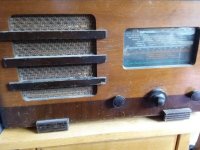
I suspect it was a cossor similar to below..in an inlaid type case.
Later examples had B7 bases, carbonised anodes, and improved ratings. The AC/Pen became a UK industry standard and was widely copied under a variety of names.
I can't remember now if it had the Pen4VA or later AC/pen on a B7 base cap or a B5, but it's not UX7 at all it's BVA (B7).
I suspect B7, so would be about 1933.
(I use B5 on my KT8Cs, another hard base to find in original UK made condition)
What was astonishing was the fact that set was still going strong in 1982+, a good solid 50yrs after being made, being used 12hrs a day..and that sitting right next to the stove in the kitchen which was coal fired.
...and my pair of GEC KT8C based (US made Bogen) amps are going strong now - better than ever after 71 years....
I don't rate any PRC made amp to be running after 5yrs never mind 10+.
My experience of anything Chinese with any form of wire or connector is catastrophic failure within anything from 2-60 months. 🙄
Attachments
Last edited:
How about actually working on them?
But what does that proof? And do you think that only you have experiences with things like this?
Since this kind of circumstantial evidence seems to mean so much to you: I'm 57 years of age. I did make amplifiers with side contact tubes (EF6, EL3, EL5). I've been a volunteer for six years in the "Rotterdams Radio Museum".
So, in your world of reasoning/'debating', is it now proven that I know more about radio than you since you only repaired one radio set some 40 years ago, or?
However quoting German literature is pointless, because the British in the 1930s were far in advance of them.
One of your countless fallacies, so typical of your way of 'debating'. Create as much smoke, distract as much as possible from the fact that you were simply wrong. I linked to the publication as proof of the introduction of the side contact base in 1934 by Philips. The publication is in German because it was meant for the German public (duh...). But it is from Philips, which ofcourse is from The Netherlands. So your 'strike' at German technology from that era is irrelevant since no German technology was involved.
I will not debate with you anymore because meaningful debate with you is impossible. Of the few claims you did on this forum that could actually be verified, too many proved to be wrong (like for example: "a 6JB5/6JC5/6HE5 is exactly the same as a 6V6"). Because of that, I doubt the rest of your claims also.
my

Don't forget the cycle clips on your trousers Mr PFL?? 😀
Some people just love to get A..n.l about their little details don't they?
I don't really give a @@(!%# as I got my old valve radio from a scrap yard for 50p...
It was a fun thing I did in school, amongst other more important things like passing lots of exams.
Nice to know you are over 16. (57)
Hope you lived a long happy life nitpicking in your tiny boring below sea level country l, 🙄 with all your little side contacts, bicycles and tulips.
I was getting really x x x xx with your constant attempted sniping anyhow.
If it's your latest hobby with your museums and guff, have a go at someone else next time.
(Oh btw don't forget it was the British who saved your Dutch Philips in 1939-40), the British who both invented the magnetron, stereo and Fm radio, and Mr Harris the thing Philips tried desperately to protect for decades for themselves.
are worth a dozen of your flat lander knickers in the twist.countless fallacies
Don't forget the cycle clips on your trousers Mr PFL?? 😀
Some people just love to get A..n.l about their little details don't they?
I don't really give a @@(!%# as I got my old valve radio from a scrap yard for 50p...
It was a fun thing I did in school, amongst other more important things like passing lots of exams.
Nice to know you are over 16. (57)
Hope you lived a long happy life nitpicking in your tiny boring below sea level country l, 🙄 with all your little side contacts, bicycles and tulips.
hoorah thank goodness for that!I will not debate with you anymore
I was getting really x x x xx with your constant attempted sniping anyhow.
If it's your latest hobby with your museums and guff, have a go at someone else next time.
(Oh btw don't forget it was the British who saved your Dutch Philips in 1939-40), the British who both invented the magnetron, stereo and Fm radio, and Mr Harris the thing Philips tried desperately to protect for decades for themselves.
Last edited:
What do you think?
Spiffy !
If I may express my one minor and entirely theoretical niggle . . . . I would put connector supports on all the valve contacts so that any accidental mechanical force borne by the valve is spread over all the contacts and not just the most needed four.
Other than that, very creative solution . I like it.
Hi Sarcastic1,
I also have been reliving the glory days of my jumble-sale-childhood by buying some old radios recently from the 30's. They crop up quite cheaply on the local auction site, and much to the chagrin of my other half, I cannot resist them.
The oldest is a Philips 834a from 1933, the next is a Paillard 768 (1935) and the most recent is a Paillart 70Tr from 1936. The Paillards had good testing RCA Arcturus 2A3 tubes for the output tubes, so the £30 quid each was not really wasted.
The point is, the way radio technology changed in the 30's was breathtaking. It must have been like breaking the bank to buy a 286 PC, then the 386 comes along 6 months later, and the 486 6 months after that. The most recent Paiilard is more or less an All American 5, which was a stock design for a couple of decades. The previous one, just 2 years younger, has wafer style switching, and a control for RF gain, that doubles as the switch for a pick-up. They are yonks apart in terms of design.
Your story about the old 30's radio bares out my experiences. The two I have tinkered with had dog bone resistors that tested fine, and it was just necessary to change the caps, and now they make perfectly good music from a CD player, with their field coil speakers. Given a long enough bit of wire I can summon up a radio station or two. They are just about bullet proof.
But in your post above you are being very non-specific about a radio you can barely remember, and being quite impolite to a guy who has dedicated a chunk of his life to a radio museum in one of the capitals of vintage electronics. I think you haqve been a bit provocative and it would not hurt to respect his knowledge and dedication a bit more.
Last edited:
 The moderation team remind you that ad hominem attacks are not welcome here.
Please read the RULES. Failure to obey the rules will find you in read only mode, or worse.
- Home
- Amplifiers
- Tubes / Valves
- Side contact sockets that actually work?