I'm working on a hybrid line stage with a tube voltage amplifier (6N6P in LTP) feeding a source follower output stage. The source follower will be cascoded and use a CCS load, with a B+ of around 250V.
Besides the higher cost, what are the pros and cons of using a SiC Mosfet for the source follower (and cascode)?
Besides the higher cost, what are the pros and cons of using a SiC Mosfet for the source follower (and cascode)?
Just watch out that many of these mosfets can switch massive currents but don't work well in the linear region. If the graphs don't provide any linear data then forget it. George (tubelab) can explain it much better than me.
SiC has several advantages for power MOSFETs used in switching converters, and the disadvantage that they have worse threshold shift due to hot carrier injection, see https://www.mdpi.com/2073-4352/12/2/245
I haven't a clue what advantage they would have in a line stage. Spirito instability (thermal instability, thermal second breakdown, the issue astouffer wrote about) is a problem with modern Si as well as SiC MOSFETs designed for switching applications, when you want to use those as an amplifying stage.
I haven't a clue what advantage they would have in a line stage. Spirito instability (thermal instability, thermal second breakdown, the issue astouffer wrote about) is a problem with modern Si as well as SiC MOSFETs designed for switching applications, when you want to use those as an amplifying stage.
Schematics?I'm working on a hybrid line stage with a tube voltage amplifier (6N6P in LTP) feeding a source follower output stage. The source follower will be cascoded and use a CCS load, with a B+ of around 250V.
Besides the higher cost, what are the pros and cons of using a SiC Mosfet for the source follower (and cascode)?
Why all the thermal concerns? These devices have been used as CCS and active loads in hundreds of projects and i don't believe anyone ever experienced issues with thermal stability.
Which silicon-carbide MOSFETs have been used like that in hundreds of projects?

I have used SiC devices in various projects before. But I have mainly stuck with SiC jfets for CCSs and other such things. They have all been thermally stable without any issue.
That all being said, IDK why we are discussing SiC devices when we are only playing with 250v? SiC devices are usually rated for 600v+.
I would also argue that the best way to do this would be to use a gyrator and a mu follower output. It's still a cathode follower for all practical purposes, but now its pulling double duty as a load. You get way more bang for your buck that way.
Thanks for the responses. I was (am) considering a SiC MOSFET only because I saw a couple of posts (can't find them now) that mentioned that the author preferred the sound compared to other power MOSFETs.
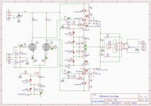
The parts are not going to be under a lot of stress, with about 50V and 15ma across them (once the tube is warmed up) and they are on a decent heatsink (each SF mosfet plus cascode shares a 7C/W HS), so I'm not too worried about thermal performance.
The SiC MOSFETs seem to have low capacitance and high bandwidth, but this doesn't necessary make them good for this application. The SiC MOSFET I was considering is the Wolfspeed C3M0280090D. Other non-SiC parts I was looking at are STP3NK60ZFP and IRFBC20PBF.
I've attached my current schematic. I have already finished the PCB layout (has not been sent to fab), so don't really want to change too much unless there is good reason to do so.
Thanks.
Attachments
Spirito instability means that even when you have a circuit that fixes the total drain current and you have adequate cooling of the whole power MOSFET, you can still get damage. Due to random variations, there is always some part of the MOSFET slightly hotter than the rest. This causes the threshold voltage of that part to decrease and the current through it to increase, which causes a further temperature increase. If this temperature increase exceeds the original temperature difference, you have positive feedback with a loop gain greater than one, and get thermal runaway; in the end, an excessively large part of the total drain current (which is supposed to be fixed by the external circuit) will flow through the hot spot and will possibly melt things. If the temperature increase is smaller than the original temperature difference, you have positive feedback with a loop gain smaller than one and everything will work fine.
You can recognize Spirito instability in the datasheet SOAR graphs as parts where the allowed current drops faster than inversely proportionally with the drain-source voltage. That's assuming the manufacturer actually characterized it properly, which is apparently not always the case.
Figure 22 of the Wolfspeed datasheet shows no sign of Spirito instability, but nothing is guaranteed beyond 100 ms. It will hopefully work fine because you stay very far below the various ratings.
Last edited:
Member
Joined 2009
Paid Member
I think this looks like an interesting project!Thanks for the responses. I was (am) considering a SiC MOSFET only because I saw a couple of posts (can't find them now) that mentioned that the author preferred the sound compared to other power MOSFETs.
The parts are not going to be under a lot of stress, with about 50V and 15ma across them (once the tube is warmed up) and they are on a decent heatsink (each SF mosfet plus cascode shares a 7C/W HS), so I'm not too worried about thermal performance.
The SiC MOSFETs seem to have low capacitance and high bandwidth, but this doesn't necessary make them good for this application. The SiC MOSFET I was considering is the Wolfspeed C3M0280090D. Other non-SiC parts I was looking at are STP3NK60ZFP and IRFBC20PBF.
I've attached my current schematic. I have already finished the PCB layout (has not been sent to fab), so don't really want to change too much unless there is good reason to do so.
Thanks.
IIRC the low capacitance region for SiC requires operation at high voltages, but used as a Follower this is not really an issue.
I would also treat reports of better sound by one author you read on the internet with as much credibility as stock recommendations from strangers on the internet. It’ll be worth exploring for yourself but I suspect bigger factors lie elsewhere in your circuit such as operating points, absence of parasitic oscillations and the load impedance being driven.
Also, I like the fact that you have allowed for a large input headroom, taking proper advantage of using tubes.
@MarcelvdG - Thanks for the info regarding the Spirito thermal effects. I wasn't aware of this and will make sure I pay more attention when operating MOSFETs in the linear domain.
I've decided that I'm going to use the IRFBC20PBF to start with. This is a relatively inexpensive part with good specs for my operating points and also has decently low thermal impedance from junction to case so I think I will be well within the safe operating area.
After doing some more research on 6N6P operating points, I've decided to increase the LTP CCS current to ~22mA which necessitated a few other component changes.
Once I get this circuit built and tested, I'll post the final schematics.
- Home
- Amplifiers
- Tubes / Valves
- SiC Mosfet for Source Follower in hybrid linestage