I have been at a bit of a standstill waiting for aluminum SMD adapter PCBs for my Lovoltech JFET projects and I was feeling bored, so I started looking for another power JFET to play with. After a bit of research, the UnitedSiC UJ3N065080K3S seemed like a good candidate to explore since I could not find a lot of info on its use in amplifiers. So, I found a LTspice model and fired up my favourite computer game and started to play.
I modeled a source follower power amp first and it appears that 20 watts output would not be too difficult. I think the Lovoltech JFET may be better performance wise, but this SiC may not need cascoding. This would need to be tested in real life.
Next, I tried to produce a reasonable common source power amp. This required cascoding for decent power output and but I wasn't happy with any of the schemes. More study is needed.
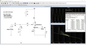
I like preamps using power devices so I had to give that a try. I ended up with a high voltage cascode with feedback. According to LTspice, with a 140V power supply, distortion is vanishingly low and output voltage swing is out-of-the-world. Off course, this is a LTspice simulation, but it was exciting none-the-less. This could be gold, or fools gold, or maybe silver.
The LTspice simu;lations got me excited enough that I ordered a couple SiC transistors so I could do some real tests.
I modeled a source follower power amp first and it appears that 20 watts output would not be too difficult. I think the Lovoltech JFET may be better performance wise, but this SiC may not need cascoding. This would need to be tested in real life.
Next, I tried to produce a reasonable common source power amp. This required cascoding for decent power output and but I wasn't happy with any of the schemes. More study is needed.
I like preamps using power devices so I had to give that a try. I ended up with a high voltage cascode with feedback. According to LTspice, with a 140V power supply, distortion is vanishingly low and output voltage swing is out-of-the-world. Off course, this is a LTspice simulation, but it was exciting none-the-less. This could be gold, or fools gold, or maybe silver.
The LTspice simu;lations got me excited enough that I ordered a couple SiC transistors so I could do some real tests.
Attachments


I received a pair of UJ3N065080K3S SiC transistors a few days ago, and was eager to see if my LTspice explorations were in a fantasy world or in a more real place. I didn't want to spend a lot of time building a complicated circuit only to be disappointed with the results, so I started with a simple self biased common source preamp with feedback.
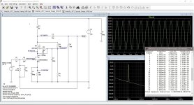
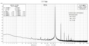
I used an inductor as the load on the drain and a source resistor for biasing. My lab power supply was used to power the circuit. I settled on 40V for power and ended up with Vds = 22V, Vgs = -9.2V, and Iq = 31 mA. With output of 2.1 Vpp, THD was 0.063%. This agreed fairly well with the LTspice simulation that I did with these operating conditions.
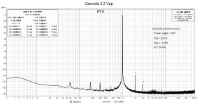
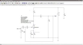
This encouraged me enough to add a MOSFET to create a cascode circuit. I didn't have a 140V power supply built, so I used the maximum output of 60V from my lab power supply. When I fired up the REW for distortion testing, I was excited to see that for 2.2 Vpp output, the total distortion had dropped to 0.0013%.
So, it looks like the UJ3N065080K3S has a future in a preamp, at least for me. I've got to do some more testing on this prototype before I increase the supply voltage, but I don't think this is fool's gold at least.
I used an inductor as the load on the drain and a source resistor for biasing. My lab power supply was used to power the circuit. I settled on 40V for power and ended up with Vds = 22V, Vgs = -9.2V, and Iq = 31 mA. With output of 2.1 Vpp, THD was 0.063%. This agreed fairly well with the LTspice simulation that I did with these operating conditions.
This encouraged me enough to add a MOSFET to create a cascode circuit. I didn't have a 140V power supply built, so I used the maximum output of 60V from my lab power supply. When I fired up the REW for distortion testing, I was excited to see that for 2.2 Vpp output, the total distortion had dropped to 0.0013%.
So, it looks like the UJ3N065080K3S has a future in a preamp, at least for me. I've got to do some more testing on this prototype before I increase the supply voltage, but I don't think this is fool's gold at least.
Attachments
I've been working on the preamp slowly, on and off, this week. I had some work done on my eyes as well, not DIY, but no more Cadillacs, I mean cataracts. Good-bye glasses.
In terms of the SiC preamp, though, I tried various combinations of low current (6 mA), higher current (50 mA), varied load inductance (47H versus 150H), power supply voltages up to 140V, and varying SiC Vds.
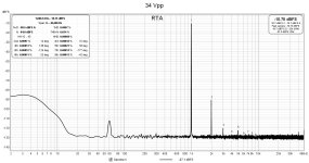
So far, the lowest distortion combination has been 140V power supply, Vds of 33V, and current of 53 mA for the SiC JFET. This results in THD of 0.0017% at 4 Vpp output and 0.0097% THD at 34 Vpp output. This is with a gain of about 4.5x. The negative feedback can be reduced for more gain and higher distortion. It depends on what a person wants. No free lunches, though. Opportunity for testing more variations.
In the end, it turns out that LTspice and the model predicted the results geneally well. The higher voltage does produce fairly low distortion.
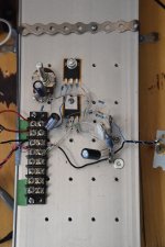
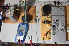
The preamp test prototype is bread-boarded rather crudely with a simple CLC linear power supply. Most of the parts were just scrounged from whatever I had around. The load inductor, though, is a nice Magnequest inductor from my parafeed tube amp days. I do have a Hammond 40H choke which I will substitute in to see how it peforms compared to the much more expensive Magnequest iron.
In terms of the SiC preamp, though, I tried various combinations of low current (6 mA), higher current (50 mA), varied load inductance (47H versus 150H), power supply voltages up to 140V, and varying SiC Vds.
So far, the lowest distortion combination has been 140V power supply, Vds of 33V, and current of 53 mA for the SiC JFET. This results in THD of 0.0017% at 4 Vpp output and 0.0097% THD at 34 Vpp output. This is with a gain of about 4.5x. The negative feedback can be reduced for more gain and higher distortion. It depends on what a person wants. No free lunches, though. Opportunity for testing more variations.
In the end, it turns out that LTspice and the model predicted the results geneally well. The higher voltage does produce fairly low distortion.
The preamp test prototype is bread-boarded rather crudely with a simple CLC linear power supply. Most of the parts were just scrounged from whatever I had around. The load inductor, though, is a nice Magnequest inductor from my parafeed tube amp days. I do have a Hammond 40H choke which I will substitute in to see how it peforms compared to the much more expensive Magnequest iron.
Attachments


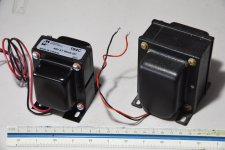
The load choke that I have been using for the preamp distortion measurements is an old Magnequest, handwound by the late Michael LeFevre. I bought a pair in the 1990s for my parafeed 2A3 tube amps. Since I decommissioned my triode amps in favour of SITs, I have been using these chokes as loads when testing transistor voltage amplifiers. They work well, but as they are no longer available and new audio chokes are quite expensive, I like to experiment with cheaper Hammond chokes.
I have used the Hammond 156C and the 157G in different voltage amplification stages and they have performed very well. So, I decided to use a Hammond choke in place of the Magnequest and I found that the Hammond 194C is quite similar in properties to the Magnequest. At 40H and 420 ohms DCR, it is quite close to the 47H and 290 ohms of the Magnequest. I bought one from DigiKey for $67 Canadian for testing. Other potential Hammond candidates include the 194E and 157G.
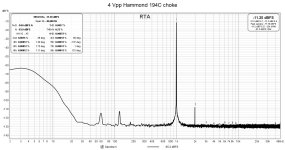
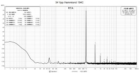
With the 194C in place of the Magnequest, I adjusted the cascode to obtain the lowest distortion for 4 Vpp 1 kHz output and made a couple of FFT measurements. The results are quite favourable. For 4 Vpp output, no real difference; at 34 Vpp output, the Magnequest is a little bit better.
I would say that in terms of engineering, the Hammond offers good value. An "audio" choke, today, would probably cost 3 or 4 times that of the Hammond. And I like that the Hammond 194C is made in Canada.
I have used the Hammond 156C and the 157G in different voltage amplification stages and they have performed very well. So, I decided to use a Hammond choke in place of the Magnequest and I found that the Hammond 194C is quite similar in properties to the Magnequest. At 40H and 420 ohms DCR, it is quite close to the 47H and 290 ohms of the Magnequest. I bought one from DigiKey for $67 Canadian for testing. Other potential Hammond candidates include the 194E and 157G.
With the 194C in place of the Magnequest, I adjusted the cascode to obtain the lowest distortion for 4 Vpp 1 kHz output and made a couple of FFT measurements. The results are quite favourable. For 4 Vpp output, no real difference; at 34 Vpp output, the Magnequest is a little bit better.
I would say that in terms of engineering, the Hammond offers good value. An "audio" choke, today, would probably cost 3 or 4 times that of the Hammond. And I like that the Hammond 194C is made in Canada.
Attachments
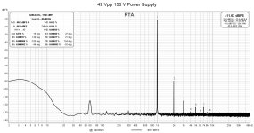
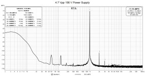
My preamp power transformer has a 120 VAC secondary and after the CLC filter, under load, the voltage is about 180 VDC. I will not use the LC filter for my final build but will use a voltage regulator. Allowing for AC line fluctuations and overhead for a voltage regulator, I think I can count on having 155 VDC available for the preamp.
The gain, with negative feedback, of my last iteration of the preamp is about 5 times. Having played around with different supply voltages, I know that increasing the supply voltage will lower distortion. So, I decided to increase the supply voltage to 155 V and decrease the negative feedback to get some gain back. The extra voltage output will be good for driving follower amps.
With these changes, I ended up with a gain of about 7.2 times. Now, with my 1 kHz oscillator's output maxed out at 6.9 Vpp, the preamp delivers 49.4 Vpp for a gain of roughly 7.2 times. The distortion numbers are about the same as for the 140 V power supply and higher negative feedback (gain = 5 x).
Attachments


I never thought of that. I'll have to fire up LTspice and give it a try. But first, I'm going to breadboard a SiC source follower with choke load. I want to drive it with the preamp and see how the combo works out.
Nice seeing other people working with this JFET. I used it in a current amp, a bit like the F2 from miniwatt, worked nicely but the heatsinks were too small... One day will put them to work again.
Have you looked into input capacitance, and frequency response with the Hammond's for PS?
Regarding the frequency response. I was thinking one could add a little RF choke (RC5900 line from Bourns, for example) in series with the PS (100Hz/120Hz) choke to improve the overall performance: when the capacitance of the PS choke starts to decrease its impedance, the RF choke can take over. Later I saw Broekie recommending this as well, so I have good hopes - but haven't tried myself yet
Last edited:
Yes, it seems like not a lot of people are actually trying out this SiC JFET. That's one reason why I decided to experiment with it.
With regards to the power supply choke, I am only using this power supply for testing. I have a voltage regulator circuit for the final design. Good idea about the RF choke, though.
With regards to the power supply choke, I am only using this power supply for testing. I have a voltage regulator circuit for the final design. Good idea about the RF choke, though.
Actually, I have barely seen it mentioned here at diyaudio. Just did a search and I think it popped up in only 5 different threads over the course of 2 years. Searching with qorvo or unitedsic did not improve the results much. Normally I am around the tube forum, and there one sees people coming up with all sort of unknown tubes and making amps out of them. Still, I am happy to see you are experimenting with it!
I see that you are using Hammond chokes that are normally used for PS filtering as chokes for audio stages. The question there is generally how these chokes, designed for 100 or 120Hz filtering, perform over the wider audio band. I once tested a Hammond 159M, and it came close to 20kHz, that surprised me. I remember Gary Pimm recommending putting two in series for higher inductance and half capacitance, so better response at both ends. Therefore, my question about your experience with the audio response of the Hammonds: do they all get to 20kHz without significant drop in response?
I see that you are using Hammond chokes that are normally used for PS filtering as chokes for audio stages. The question there is generally how these chokes, designed for 100 or 120Hz filtering, perform over the wider audio band. I once tested a Hammond 159M, and it came close to 20kHz, that surprised me. I remember Gary Pimm recommending putting two in series for higher inductance and half capacitance, so better response at both ends. Therefore, my question about your experience with the audio response of the Hammonds: do they all get to 20kHz without significant drop in response?
I like trying out new things and I hope that writing about my experiences will encourage other people to explore more. I think that writing about what doesn't work is also important and that's why I tend to run on a bit.
I have used Hammond chokes as drain and source loads in several transistor amplifiers and I have found that their high frequency performance is quite good. I think the low driving impedance of the transistors helps a lot. When I first decided to try choke loading a few years ago, I attempted to buy an "audio" choke from a transformer winder. He emphatically told me that I was wasting my time. That lead me to trying Hammond chokes, and I'm glad I did.
The other Hammond chokes that I have used include the 156C, 157G, 193U, and 193V. I'm not the only one using Hammonds, and others even use the primary windings of microwave transformers as loads (see Mofo).
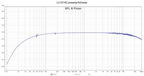
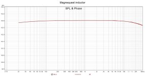
I have measured the frequency responses in other amplifier projects and you can find them on other diyAudio threads. For a quick look-see, I've included a couple of measurements here for my Lovoltech preamp and follower power amp which both use Hammond inductors as loads and you can see the frequency responses. The first graph shows the response of the preamp, while the second graph shows the response of the preamp and power amp together.
I have used Hammond chokes as drain and source loads in several transistor amplifiers and I have found that their high frequency performance is quite good. I think the low driving impedance of the transistors helps a lot. When I first decided to try choke loading a few years ago, I attempted to buy an "audio" choke from a transformer winder. He emphatically told me that I was wasting my time. That lead me to trying Hammond chokes, and I'm glad I did.
The other Hammond chokes that I have used include the 156C, 157G, 193U, and 193V. I'm not the only one using Hammonds, and others even use the primary windings of microwave transformers as loads (see Mofo).
I have measured the frequency responses in other amplifier projects and you can find them on other diyAudio threads. For a quick look-see, I've included a couple of measurements here for my Lovoltech preamp and follower power amp which both use Hammond inductors as loads and you can see the frequency responses. The first graph shows the response of the preamp, while the second graph shows the response of the preamp and power amp together.
Attachments

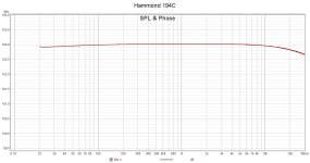
It's said that the proof of the pudding is in the tasting. In this case, it will be the testing. Since the preamp is just breadboarded, and I have both the Hammond and Magnequest chokes handy, it was easy to run frequency response tests on each using REW.
Here are the results. Not much difference. The Hammond's response may even look a little flatter.
Here are the results. Not much difference. The Hammond's response may even look a little flatter.
Attachments
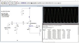
I made a little more progress today. I was pretty happy with the preamp, so it was time to put together a source follower power amp. Given that I was going to use my lab power supply for the negative bias as well as the positive supply, there were not many parts to scrounge and assemble.
I had a Hammond 193U choke on hand (200 mH, 1.7 ohm, 2A) so I used that for the source load. It all went together fairly quickly and after some wiring checks, I hooked up the test 1 kHz signal, oscilloscope, bias power supply and started the testing. After carefully juggling the two power supply voltages and the current limiting function (nice feature), I managed to stabilize the operating point.
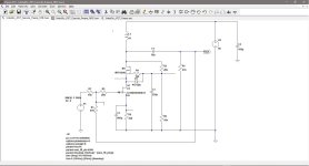
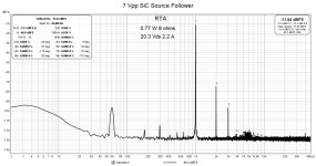
I ended up with a positive supply voltage of 24V, bias of -4.3V, which resulted in Vds of 20.3 V and quiescent current of 2.2 amps. This works out to power dissipation of 45 watts. I have included the LTspice simulation for this operating point in case anyone is interested.
Distortion measurements with REW showed THD of 0.068% at power output of 0.77 watts into 8 ohms. My oscillator only puts out just over 7 Vpp so that limited the maximum power output tested.
That was enough excitement for the day, so I quit before I did something stupid.
I had a Hammond 193U choke on hand (200 mH, 1.7 ohm, 2A) so I used that for the source load. It all went together fairly quickly and after some wiring checks, I hooked up the test 1 kHz signal, oscilloscope, bias power supply and started the testing. After carefully juggling the two power supply voltages and the current limiting function (nice feature), I managed to stabilize the operating point.
I ended up with a positive supply voltage of 24V, bias of -4.3V, which resulted in Vds of 20.3 V and quiescent current of 2.2 amps. This works out to power dissipation of 45 watts. I have included the LTspice simulation for this operating point in case anyone is interested.
Distortion measurements with REW showed THD of 0.068% at power output of 0.77 watts into 8 ohms. My oscillator only puts out just over 7 Vpp so that limited the maximum power output tested.
That was enough excitement for the day, so I quit before I did something stupid.
Attachments
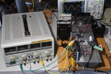
Over the last couple of days, I have been testing and troubleshooting my SiC preamp and source follower power amp combo. The power amp is partially self biased with the source inductor DC resistance and augmented with a negative voltage fixed bias at the gate.
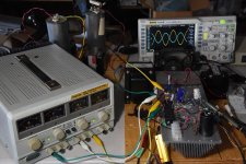
My dual voltage lab power supply is good for 2 x 30 volts at 3 amps. It has constant current capabilities so it provides some protection against catastrophic runaway. When I started testing the integrated amplifier, everything went smoothly. I managed to dial in a nice operating point with a power supply output of 24 volts and quiescent current of about 2.3 amps.
However, as I increased the amp's power output, the lab power supply indicated that current limiting was taking place. This puzzled me as I had set the current limit to the maximum of 3 amps on the power supply. I was concerned, and I started thinking bad things. Oscillations? Issues with the SiC transistor that I'm not familiar with? At any rate, I was not comfortable with proceeding without find the cause of this behavior.
Checks with my voltmeter gave no clue. I could not find any oscillations with my oscilloscope. Finally, probing the 24 volt power supply line with my oscilloscope, I could see a sine waveform with spikes. Thinking more about this, I realized that when the output voltages peak, the current is much more than 3 amps, and the power supply was reacting.
I did have a local 470 uF decoupling capacitor at the amp breadboard, but it was not sufficient to isolate the power supply from the amp. After I increased the capacitance to 4700 uF, everybody was happy, including me. I guess the moral of the story is that the power supply is very important. You are what you eat.
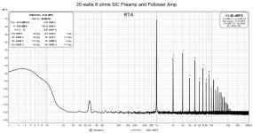
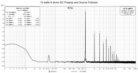
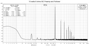
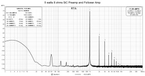
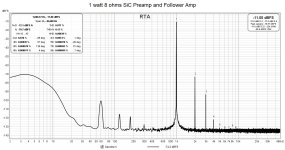
With that worry banished, I completed my distortion tests on the combined SiC preamp and source follower power amp. THD at 1 watt out into 8 ohms measured 0.077%, and above 20 watts, distortion started increasing rapidly. I didn't chase the 1 watt distortion number, so it probably can be improved at the expense of something else.
The SiC JFET operating point was operating at Vds = 20.0 V, Iq = 2.3 A. The bias consisted of 4.0 V at the source and -4.3 V at the gate.
My dual voltage lab power supply is good for 2 x 30 volts at 3 amps. It has constant current capabilities so it provides some protection against catastrophic runaway. When I started testing the integrated amplifier, everything went smoothly. I managed to dial in a nice operating point with a power supply output of 24 volts and quiescent current of about 2.3 amps.
However, as I increased the amp's power output, the lab power supply indicated that current limiting was taking place. This puzzled me as I had set the current limit to the maximum of 3 amps on the power supply. I was concerned, and I started thinking bad things. Oscillations? Issues with the SiC transistor that I'm not familiar with? At any rate, I was not comfortable with proceeding without find the cause of this behavior.
Checks with my voltmeter gave no clue. I could not find any oscillations with my oscilloscope. Finally, probing the 24 volt power supply line with my oscilloscope, I could see a sine waveform with spikes. Thinking more about this, I realized that when the output voltages peak, the current is much more than 3 amps, and the power supply was reacting.
I did have a local 470 uF decoupling capacitor at the amp breadboard, but it was not sufficient to isolate the power supply from the amp. After I increased the capacitance to 4700 uF, everybody was happy, including me. I guess the moral of the story is that the power supply is very important. You are what you eat.
With that worry banished, I completed my distortion tests on the combined SiC preamp and source follower power amp. THD at 1 watt out into 8 ohms measured 0.077%, and above 20 watts, distortion started increasing rapidly. I didn't chase the 1 watt distortion number, so it probably can be improved at the expense of something else.
The SiC JFET operating point was operating at Vds = 20.0 V, Iq = 2.3 A. The bias consisted of 4.0 V at the source and -4.3 V at the gate.
Attachments

Nice and congratulations! My amp had an active load and therefore double the heat - the choke has a clear advantage here.
Thank you.
Maybe this will entice you to try a choke in your amp. You could reduce your power supply voltage and your small heatsink may be big enough.
Maybe this will entice you to try a choke in your amp. You could reduce your power supply voltage and your small heatsink may be big enough.
At some point, a new amplifier must be listened to in order to evaluate it. So yesterday, I decided it was time to taste the pudding. After all, it is the proof.
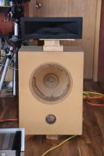
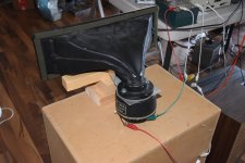
I hooked the preamp and amp to my go-to test speaker which consists of a scavenged 12 inch speaker in a 2.8 or so cubic foot vented box in combination with an 1" Altec compression driver and horn. The cross over is an Altec 800 Hz unit. It's a bit crude looking but it produces good sound with low distortion and can go loud. In short, it's a great party speaker.
The program source was a 3-in-1 boom box with headphone out connected to the preamp. I used my old collection of CDs for the program material. Given that they are CDs, they truly are old farts' music.
I listened to quite a selection of music over two days and that probably added up to 5 hours worth. This speaker system and boom box source is what I usually use for amp testing so I'm familiar with its sound.
Right off the bat, I noticed the strong, powerful sound from the system. Music from Sade and Madonna thumped out nicely. Paul Simon's Graceland cranked out throatily. I still remember when I heard this album played on a turntable through megawatt amplifiers with double stacked Advent speakers sometime in the early 1980s. This wasn't quite at that level but the feeling was there.
I found a Telarc CD of Strauss waltzes and I put that on. This CD has extreme dynamics including percussive sound effects and the system reproduced these well. I did notice that my lab power supply's current limiting indicator light was flickering on peaks. The CD booklet actually warns about possible damage to equipment when playing the content and to start at a low volume level.
Today, after about another hour of listening, I traded out the SiC power amp for my Lovoltech JFET power amp. It, too, is a source follower but with lower power output. After listening to it for a few cuts, I could not point out any significant differences between the two power amps. So, I would say they have similar sound.
I have compared the Lovoltech amp to my SIT/VFET amps driving my Quad ESL speakers and I found that they are quite similar, so logically, the SiC amp probably compares well to the SIT/VFET amps also.
After testing and listening to these SiC amps, I have decided that I will build finished versions. But first, I will reconfigure the source follower amp and test the SiC in common source configuration.
Attachments

- Home
- Amplifiers
- Pass Labs
- SiC Adventures - Exploring the UJ3N065080K3S