OK... so I'm having trouble understanding how to accomplish these two objectives as it relates to getting a Shure WL93 lav mic and a Point-Source Audio CO-6 earset mic to plug into a standard mixer:
1. drop 48V phantom power down to ~5V
2. maintain audio signal integrity (i.e. no appreciable loss or blockage)
The issue is that the mixer input impedance is only 3400 Ohm and I'm also not sure I've got the wiring figure out correctly.
Here's what I whipped up as an idea. Did I get the wiring right? Did I get the component values right?
An externally hosted image should be here but it was not working when we last tested it.
The impedance of the microphones has very little to do with their d.c. specifications.
Your circuitry will not reduce the 48 volts to 5 volts. In most cases, the 48 volts is supplied through a pair of 6.8k resistors ... one resistor on each side of the mixers balanced audio input. To reduce the phantom voltage, you will need two 'tee' networks. One on each side of the balanced microphone circuit. The shunt legs of the tee networks should go to pin 1 ground. To keep the tee networks from attenuating the audio, you should bypass the series legs with suitable capacitors. The tee network resistor values will depend on the d.c. current demand of the microphones.
Your circuitry will not reduce the 48 volts to 5 volts. In most cases, the 48 volts is supplied through a pair of 6.8k resistors ... one resistor on each side of the mixers balanced audio input. To reduce the phantom voltage, you will need two 'tee' networks. One on each side of the balanced microphone circuit. The shunt legs of the tee networks should go to pin 1 ground. To keep the tee networks from attenuating the audio, you should bypass the series legs with suitable capacitors. The tee network resistor values will depend on the d.c. current demand of the microphones.
I had wondered about the resistors doing anything, so thanks for clarifying that. Are you suggesting this kind of a circuit?
Bias tee - Wikipedia, the free encyclopedia
Bias tee - Wikipedia, the free encyclopedia
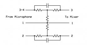
No. You will need three resistors on each side of the balanced circuit. I'll draw it up and post it soon.
Thanks. I think I've been imagining the roles of components incorrectly. Is it correct visualization that the caps will not neutralize the DC voltage but block it, forcing them to go through the resistors which are creating a voltage divider circuit? Is it also correct in thinking that the resistors nearest to the microphone will cause the audio signal to want to travel across the caps instead of entering the divider circuit?
This looks great. Thanks.
This looks great. Thanks.
Last edited:
Hi Ethan,
As an alternative you might want to try an off-the-shelf solution which is a line-level converter that will work with both our CO-6 and the Shure lav. We offer this accessory for the earset microphones and it should work with your lav as well. The item number is CON-XLR at the bottom of this page http://www.pointsourceaudio.com/earset_microphone_accessories.html. Please do not hesitate to email our support team with any questions support@point-sourceaudio.com. Thank you.
As an alternative you might want to try an off-the-shelf solution which is a line-level converter that will work with both our CO-6 and the Shure lav. We offer this accessory for the earset microphones and it should work with your lav as well. The item number is CON-XLR at the bottom of this page http://www.pointsourceaudio.com/earset_microphone_accessories.html. Please do not hesitate to email our support team with any questions support@point-sourceaudio.com. Thank you.
Thanks. I think I've been imagining the roles of components incorrectly. Is it correct visualization that the caps will not neutralize the DC voltage but block it, forcing them to go through the resistors which are creating a voltage divider circuit? Is it also correct in thinking that the resistors nearest to the microphone will cause the audio signal to want to travel across the caps instead of entering the divider circuit?
This looks great. Thanks.
The caps are there to bypass the d.c. voltage attenuation circuit.
The audio will go through the caps while the d.c. is attenuated by the resistors.
There will be a little audio attenuation but not enough to cause problems for you.
- Status
- Not open for further replies.
- Home
- Live Sound
- PA Systems
- Shure TA4F to XLR-M wiring