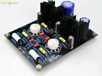
Would it be this one perhaps? HIFI Tube MM RIAA Turntable Phono preamplifier kit base on SHUER M-65 --L10-46 | eBay
No spec, just working voltages. Cheap knock off stuff and they can't even get the descriptive name right or is that to avoid copyright ....
No spec, just working voltages. Cheap knock off stuff and they can't even get the descriptive name right or is that to avoid copyright ....
The problem is that the output impedance of this item is high.
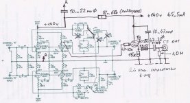
See the attatched schamatics
I'm not sure thats the case - the schematic you've posted clearly doesn't have the voltage reg and other bits of sand that are provided on the clone. Is it possible that some of that sand provides a low impedance output buffer?
> bits of sand that are provided on the clone. Is it possible that some of that sand provides a low impedance output buffer?
I do not see any sand between the tube and the output. The regulators would probably give clean B+ and Heater; this does not change the amplifier.
While Shure claimed <5k at 10KC output, this is incomplete. The raw output impedance is near 39k. The NFB reduces this. By the nature of RIAA NFB, we have great gobs of NFB at the top of the band, and are likely to be shy of NFB at the bottom of the band. The 7.5Meg NFB resistor (where ideally we'd have ~~1Meg) confirms the thing has run low on NFB before 50Hz. So probably 35k@50Hz, 4k@1KHz, 400r@10KHz.
+Plus+ the 0.05uFd output cap (which appears to be unchanged). Adds another 40k @ 50Hz, 4k @ 500Hz.
If loaded in 1Meg (1960 tube amp input), all of this is fine.
If loaded in 10k (not unknown today) it will fall-off bad below 500Hz.
If they are going to "tribute" an old cheap utility amplifier, today, I do think it would be kind to add a buffer for today's lower impedances. But I doubt they know or care.
One don't expect low impedance from a 12ax7 . The schematics reminds ofI'm not sure thats the case - the schematic you've posted clearly doesn't have the voltage reg and other bits of sand that are provided on the clone. Is it possible that some of that sand provides a low impedance output buffer?
dynaco PAS PC-6 ( phone stage ), a very good phono stage but best used
with 250k loading.
> Is it possible that I change the output impedance with a third tube or possibly with a transistor?
Yes (a tube or transistor)..... but then why did you buy a low-price kit? By the time you hack this up (possibly including more heater power) you could have started from a more suitable kit or DIY project.
Yes (a tube or transistor)..... but then why did you buy a low-price kit? By the time you hack this up (possibly including more heater power) you could have started from a more suitable kit or DIY project.
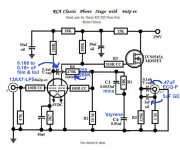
Shure clone schematics
Unfortunately, I bought this, I'm very beginner.
I found a drawing with a modification.
Unfortunately, I bought this, I'm very beginner.
I found a drawing with a modification.
Attachments
The power transformer rectifier winding seems competent and (hopefully) drawing a few additional mA. from the B+ supply will not be problematic. OTOH, adding to the demands placed on the heater supply could easily cause trouble.
Instead of using the sections of a 12AU7/ECC82 as the basis of buffering voltage followers, use pairs of DN2540N3 depletion mode MOSFETs wired in cascode as the basis of the buffering voltage followers. FETs eliminate all issues associated with heaters. Why cascode? The cascode arrangement "eliminates" adverse gate/drain interactions to maximize linearity across the audio band.
Instead of using the sections of a 12AU7/ECC82 as the basis of buffering voltage followers, use pairs of DN2540N3 depletion mode MOSFETs wired in cascode as the basis of the buffering voltage followers. FETs eliminate all issues associated with heaters. Why cascode? The cascode arrangement "eliminates" adverse gate/drain interactions to maximize linearity across the audio band.
My drug is not worn-off so maybe I am spouting crap.....
I can't see any fault in a simple "cathode" follower considering all the curvature in *two* 12AX7 gain-stages. Simplicity is a virtue. Especially for a "very beginner".
The major fault here is that two 12AX7 gives gain of say 3,000 max, while the RIAA NFB is scaled for gain of 100 @ 1KHz and thus 1,000 <50Hz. So there's not really enough NFB for precise EQ or low bass THD.
But wait, there's more. Neither stage has cathode caps. Pencil gain more like 1,000. Yes, there is the PFB inter-cathode resistor which nominally increases gain. I believe Norman Koren analyzes this very well (in context of the similar Dyna preamp).
The output stage current is just 0.3mA, very small for modern loads. The output cap is also small for full bass in modern loads.
AND there is 0.25V of DC on the output! Via 7.6Meg (30mV in 1Meg load) so maybe it never bothered anybody; it's still bad practice.
K.I.S.S. Remove C6. Put a small high-V NPN in there (NPN needs less protection than MOSFET) and an emitter resistor. This can all be air-wired above the PCB. Put a decent coupling cap in the wire to the output jack.
The BJT runs at 1.4mA so hIE is near 20r. Into a heavy 14k total load there's 56dB internal NFB. At FULL output the follower's THD is 0.04%. We should never be 1/4th of full output so pencil 0.01% THD naked. This is further reduced by overall NFB (but not-much at 50Hz).
The 12AX7es will be several-Tenths % THD on loud passages.
MPSA42 (random Amazon link) is an old reliable 300V NPN.
Attachments
I wasn't comfortable (not knowing enough) to drive the NFB EQ from the follower. So, I thought cap. couple the setup, as is, to the buffer. Since DC coupling the buffer to the 2nd gain block is a non-issue, thought can be given to "borrowing" the enhancement mode MOSFET buffer used in the tweaked RCA phono preamp. The tiny and stable capacitances of the ZVN0545A are no problem, whatsoever, for a 'X7 section to drive. So, cascoding is not needed. In addition, the FET will present a desirable much higher impedance to the triode than a BJT.
There is a "gotcha" associated with DC coupled enhancement mode voltage followers. A protective Zener diode is required between the gate circuitry and the source, as power on conditions are unfavorable. A 1 W. rated, 12 V., part is appropriate in combination with the ZVN0545A.
PRR, is correct about a substantial O/P coupling cap. being needed. 3.3 μF. is the absolute minimum for working into the IHF "standard" 10 Kohm load. Think lowest common denominator. I recommend a 4.7 μF. metalized polypropylene part bypassed by a 0.47 μF. 716P "Orange Drop" film & foil part. That combination is cost effective and works well.
Attachments
Last edited:
> 3.3 μF. is the absolute minimum for working into the IHF "standard" 10 Kohm load.
10K is really-really too much for this amp. I was hoping for 22k, which is where I got the 14k loading for THD thumb-reckoning. 0.5uFd in 22k is 15Hz.
There is GROSS bass error in this plan, easily 6dB (either way) in the 20Hz-70Hz zone, so I am not upset by another -1dB @ 30Hz.
Remember 1960? BIG mis-tuned bass reflex woofers, the Williamson's tendency to sub-sonic bump, hard fiberglass window curtains, etc. There's a reason we all USED the bass-knob. Mostly UP (to unrealistic boost), but sometimes down (to keep from booming knickknacks off the shelves). The Shure is typical of a bad lot.
The M65 circuit is actually capable of very nice audio quality, but the output loading limitations must be respected. For some hands-on experience, look on AudioAsylum for posts by “InterstageTranny.” I built a hardwired M65 phono following ITranny’s advice and using top quality parts, and it is an excellent performer with a 100K load.
As far as I am concerned, the Chinese copy isn’t a clone at all. It just uses a similar audio schematic. A real M65 has AC powered heaters, a selenium rectifier for the B+, very low B+ voltage, and ultra-compact point-to-point wiring.
As far as I am concerned, the Chinese copy isn’t a clone at all. It just uses a similar audio schematic. A real M65 has AC powered heaters, a selenium rectifier for the B+, very low B+ voltage, and ultra-compact point-to-point wiring.
- Status
- This old topic is closed. If you want to reopen this topic, contact a moderator using the "Report Post" button.
- Home
- Amplifiers
- Tubes / Valves
- Shure M65 and clones