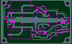
I am looking to build a +/- 15V power supply for a preamp project. I wanted to try something with a shunt regulator but with a minimum of parts. I found this circuit by John Broskie and made a few modifications. I added a LM317 as a CCS to limit the output to ~300mA. I also used a LM317 on the negative side as the LM337 has rather poor AC rejection above about 5KHz. I added the zener's to get bit better regulation. The output across the shunt should be about 15V(14.95). It appears to work OK on LT Spice. Any suggestions?
Attachments
tkwou What parts were you thinking of for the zeners? What is nessisary in terms of accuracy of regulation of the zeners to beat what you would have with just a LM317 and resistors? I know no reason why it would not work as drawn.
Thanks firechief. No it does work fine as drawn. I added the zeners between the output rails and the LM317,LM337 adjuster pins. The original schematic only used a resistor to create the voltage divider. I thought the zeners would give a little better regulation. Would it be of much benefit to use a constant current device to replace the currrent limiting resistors for the zeners?
Quoting from the National Data sheet
Guaranteed 1% output voltage tolerance (LM317A)
Guaranteed max. 0.01%/V line regulation (LM317A)
Guaranteed max. 0.3% load regulation (LM117)
I wonder if the added zeners are doing any good. Have you got some in mind? Would the accuracy of the zeners contribute in a positive way to the oevrall regulation? And now I am at my knowledge limit on this subject. I sure wish someone else would jump in here 😕
The LM317 should give very good regulation on their own. It uses a bandgap device for the 1.25V reference and resistors in voltage divider to set the voltage. I have noticed in their AN sample circuits that they will use a second bandgap attached to the adjust pin for tighter regulation and temperature stability. That's the only reason I used the zeners my circuit. The circuit would have worked just fine using just resistors.
yes, nice circuit from John Broskie (tubecad.com).
LINK1
LINK2
Two zeners should be replaced with single one. Or with LED's. Or any other low noise voltage reference.
10K resistors can be replaced with CCS. Capacitors for bypassing reference voltage should be "low-leakage current" type. No solid polymers there. Adjustment pin for regulators can be further filtered, like this LINK3
Last edited:
Hello tkwou. Did you do the source? Worked ok?
I am looking for something like for my Buffalo II dac.
Regards.
Jose
I am looking for something like for my Buffalo II dac.
Regards.
Jose
omit 5 WATT resistors and 5 volt supply associated components if only 15 volts+/-
supply is needed 2200uf should be 35 volts please
warm regards
andrew lebon
supply is needed 2200uf should be 35 volts please
warm regards
andrew lebon
- Status
- Not open for further replies.
- Home
- Amplifiers
- Power Supplies
- Shunt regulator using LM317 & LM337

