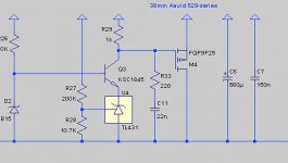
I'm looking at a 49V shunt regulator that I've adapted from a design by Pete Millet:

When I run an AC analysis on it, I get an ugly spike at 280kHz where I lose almost 20dB of attenuation:

I can mostly smooth this out by using an ultra-low-impedance electrolytic capacitor for C8. Here's what it looks like with a 0.038 ohm ESR cap:

But that's an awfully specialized cap and it doesn't seem like this circuit should be that finicky. Is there a better way to handle this?
Thanks,
Jeff.
When I run an AC analysis on it, I get an ugly spike at 280kHz where I lose almost 20dB of attenuation:
I can mostly smooth this out by using an ultra-low-impedance electrolytic capacitor for C8. Here's what it looks like with a 0.038 ohm ESR cap:
But that's an awfully specialized cap and it doesn't seem like this circuit should be that finicky. Is there a better way to handle this?
Thanks,
Jeff.
I can damp the -52dB spike with either a really big stopper (12K) or a Zobel over the collector resistor. Neither helps the -60dB hump following the spike. Both move the spike to a lower frequency.
Increasing the current through the TL431 moves the spike to a higher frequency.
Dropping the TL431 current to 2.5mA (TI's minimum spec is 1mA) and using a 680ohm gate stopper moves the spike low enough that a more "normal" electrolytic can knock it to -64dB.
Is this worth doing, or is this more likely just SPICE playing with my head?
Thanks,
Jeff.
Here we have:
blue: original
red: stonkin' big 12K gate stopper & higher TL431 current
cyan: original with ultra-low impedance electrolytic (Nichicon UHW)
green: stonkin' big 12K gate stopper with ultra-low impedance electrolytic
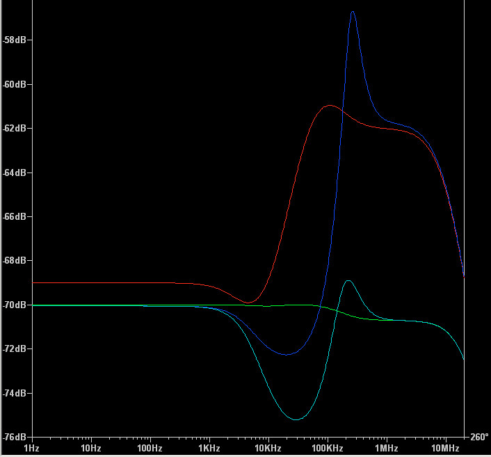
Are there any issues with such a big gate stopper? 'Cause the green curve sure looks nice....
blue: original
red: stonkin' big 12K gate stopper & higher TL431 current
cyan: original with ultra-low impedance electrolytic (Nichicon UHW)
green: stonkin' big 12K gate stopper with ultra-low impedance electrolytic
Are there any issues with such a big gate stopper? 'Cause the green curve sure looks nice....
Attachments
Spice can help you see the effect of changing or adding components. What it won't do, unless you tell it, is model the effects of the parasitics of the actual real circuit which you may one day build. At present what you are mainly seeing is the component parasitics included in the Spice models, which will vary a bit from sample to sample anyway.
Assuming the parasitics of the devices are reasonably modelled, one parasitic to look out for is the C across R27. Try with say 3pF across R27, see what that does to the original, then try again the other things.
The zobel from gate to drain should have exactly the same effect as the same zobel across the collector R.
Jan
The zobel from gate to drain should have exactly the same effect as the same zobel across the collector R.
Jan
@Jan, yes, you're right: I now get the same result with the Zobel across the collector R. Not sure why I didn't the first time around.
Adding 3pF across R27 actually improves the original response slightly. The relative additional improvements of the 12K stopper vs. the Zobel remain more-or-less unchanged.
Adding 3pF across R27 actually improves the original response slightly. The relative additional improvements of the 12K stopper vs. the Zobel remain more-or-less unchanged.
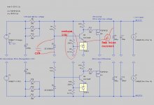
This regulator is a cascade of three individual stages
Stage1 is an inverting amplifier with lots of gain: the TL431 integrated circuit. Input is a fraction of the regulated voltage, output is the cathode-to-anode current, which changes the VBE of the NPN
Stage 2 is a noninverting amplifier with a moderate amount of gain: the NPN transistor operated as a common base stage. Input is the emitter voltage (which changes the VBE since the base is at a fixed reference voltage), output is the (Icollector * Rload).
Stage 3 is a noninverting amplifier with unity gain: the MOSFET source follower.
Connected end to end, the cascade has lots of gain and more-than-usual opportunities (3 stages!) to add unwanted phase shift. It's not a huge surprise if the result shows marginal stability / unwanted resonances. Which can be fixed by three weeks of hard work using control theory and Laplace analysis. But you have to be Pete Millett and possess an EE degree to do that work.
Next best might be to improve the individual stages by running them at higher current. Higher current -> faster charging of intrinsic capacitances -> less phase shift -> greater stability. Three low hanging fruits are shown on the diagram below. I make no guarantees it will actually solve the problem; for that you need Pete Millett or someone willing to do a lot of work on Pete's circuit. Me? no thanks.
_
Attachments
Cool ideas, @Mark. The CCS to the cathode of the TL431 drops the noise floor a couple of dB -- although it doesn't alter the "hump". The 10X lower resistor values has a much more modest improvement, and the Zener bypass none at all (does SPICE not model Zener noise?).
I already tried higher current -- it helps the hump a little but at greater expense to the floor over the audio band.
@Jan, I was at first using 0.11ohms for C8's ESR. The Nichicon UHWs drop that to 0.049 ohms, which has shown the biggest improvement in the circuit so far.
By "delete C1 and C13" do you mean just for the sim, or entirely? (I had wondered if I was suffering parasitic oscillation between the electro and film, but removing the film didn't change anything.)
Thanks for all the pointers, guys! I do appreciate it.
Normally you need some lossy stuff at the output and an electrolytic does that for free. Bridging that with a high-quality film could negate that and lead to instability.
I have had that happen to me many times, and often the removal of the ESR-free film fixed it.
Worth a try.
Jan
I have had that happen to me many times, and often the removal of the ESR-free film fixed it.
Worth a try.
Jan
Poking at the "lossy stuff" comment, I made a rather remarkable improvement by simply swapping the caps and isolating them. No need for the Zobel; bog-standard gate stopper.
Positive rail has the above change, and produces the green trace. Negative rail has the previous Zobel improvement, and is plotted in blue.
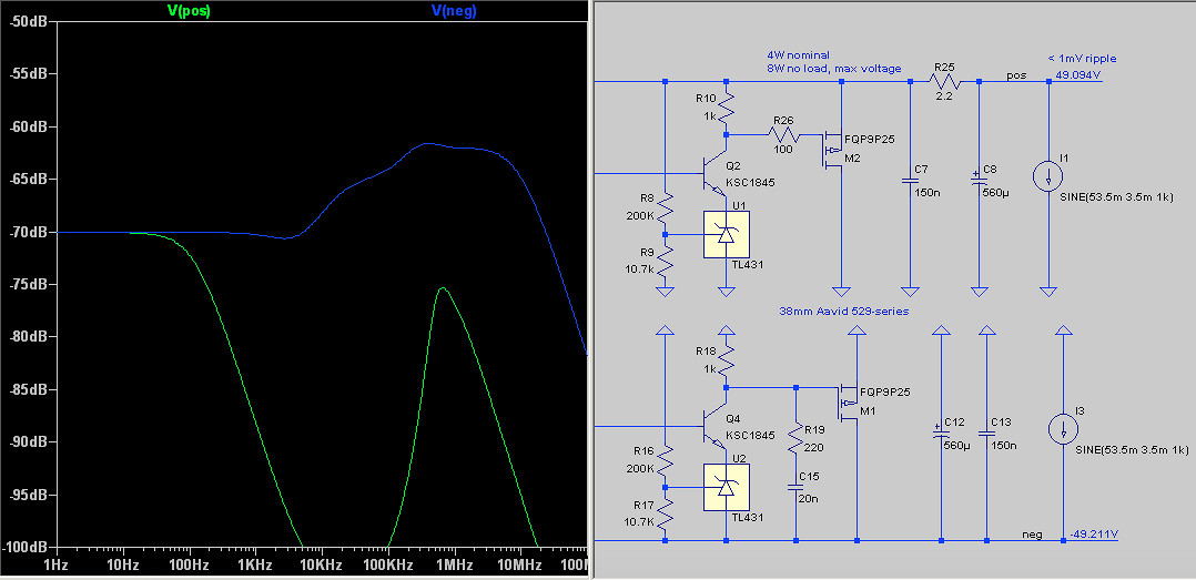
Positive rail has the above change, and produces the green trace. Negative rail has the previous Zobel improvement, and is plotted in blue.
Attachments

- Status
- This old topic is closed. If you want to reopen this topic, contact a moderator using the "Report Post" button.
- Home
- Amplifiers
- Power Supplies
- Shunt regulator PSRR dropout?