Mix and Match
Combining the improvements in both the series and shunt elements, we have an opportunity to create as simple or as complicated a circuit as we need.
Here is a very simple low feedback design. This is just one example of what is possible.
It’s virtually mix and match with any of the circuits presented.
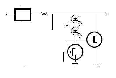
Here is the Salas Version 1.1; I consider this to be very good engineering.
The circuit is stable, not sensitive to parts or layout, and not insanely complex.
The original is in the DIYaudio thread simplistic-salas-low-voltage-shunt-regulator, post 501.
http://www.diyaudio.com/forums/powe...w-voltage-shunt-regulator-51.html#post1855189
As you can see, you can make this as simple or complicated as you need.
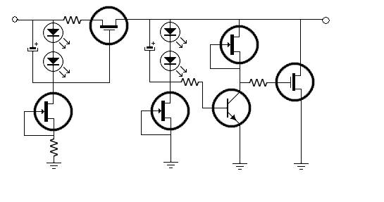
Performance:
Notice that in the circuits I did not give much guidance as to which was “better”.
That is by design. The circuits are simple enough to try several variations.
It’s clear to me that a Better CSS will reject ripple better.
It is clear that a higher feedback shunt will have a lower output Z.
It’s also clear that high feedback can threaten high frequency stability.
When feeding a circuit that has a high PSRR, simplicity and stability may be priorities.
For something high gain and low signal, the lower Z may be mandatory.
One size may not fit all.
Additional current through the regulator can improve the regulator’s stability, ripple margin and device gain.
However, is increases heat, power consumption and may require bigger, more expensive, less ideal parts.
There are other factors. The current through the shunt should be greater than the maximum the load could draw.
Also, for the FET example, the FETs have more Gm with higher current. So a practical shunt runs with “extra” current.
Remote sensing is required if the regulator needs to be physically separated and the desired output Z is close to the Z of the wire.
Combining the improvements in both the series and shunt elements, we have an opportunity to create as simple or as complicated a circuit as we need.
Here is a very simple low feedback design. This is just one example of what is possible.
It’s virtually mix and match with any of the circuits presented.
Here is the Salas Version 1.1; I consider this to be very good engineering.
The circuit is stable, not sensitive to parts or layout, and not insanely complex.
The original is in the DIYaudio thread simplistic-salas-low-voltage-shunt-regulator, post 501.
http://www.diyaudio.com/forums/powe...w-voltage-shunt-regulator-51.html#post1855189
As you can see, you can make this as simple or complicated as you need.
Performance:
Notice that in the circuits I did not give much guidance as to which was “better”.
That is by design. The circuits are simple enough to try several variations.
It’s clear to me that a Better CSS will reject ripple better.
It is clear that a higher feedback shunt will have a lower output Z.
It’s also clear that high feedback can threaten high frequency stability.
When feeding a circuit that has a high PSRR, simplicity and stability may be priorities.
For something high gain and low signal, the lower Z may be mandatory.
One size may not fit all.
Additional current through the regulator can improve the regulator’s stability, ripple margin and device gain.
However, is increases heat, power consumption and may require bigger, more expensive, less ideal parts.
There are other factors. The current through the shunt should be greater than the maximum the load could draw.
Also, for the FET example, the FETs have more Gm with higher current. So a practical shunt runs with “extra” current.
Remote sensing is required if the regulator needs to be physically separated and the desired output Z is close to the Z of the wire.
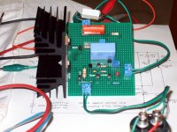
Attachments


Last edited:
Higher current through v1.2 will easily lead to instability because of the higher gain at higher frequency (you can blame the buffer which extends the bandwidth). v1 does not suffer of this problem. That's what I think, although I haven't built v1.2 yet.
However, I haven't thought of the compensation which I'm told brings the regulator to stability. So I retract my previous comment.
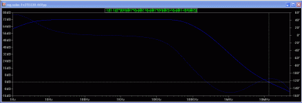
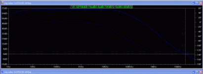
Here are two simulation indications. Run on V1.2 TO-220 IRF9610 & 9540 46Vo with 10uF film cap for the Norton Vref decoupling and 4u7 film cap with 1R locally across reg's output. There is a lead-lag step network compensating the error amplifier. To the left at 200mA. To the right at 1A. 10 degrees of PM loss. Its not meant to run on amps due to the heat inefficiency, thus the lighter/faster CCS Mosfet, but I checked it out on the sim just for the sake of argument. If a heavy duty application comes to mind, the gate stoppers and the comp can always be centered around large current and TO-247 Mosfets. I would not think that the signal levels on a power amp will justify more than a V1.0 if a shunt is wished to power it though.
Attachments
Would you elaborate a little bit more on the sense wire connections ?
Theoretically I know why we need it and I can confirm the benefits ( I have built more than 20 V12R), but would like to have a clearer idea on how it works.
Theoretically I know why we need it and I can confirm the benefits ( I have built more than 20 V12R), but would like to have a clearer idea on how it works.
We want the reg's error amplifier to measure correctly the impedance at the actual load's nodes. It's exactly like when we want to do precise resistance measurements with a multimeter. We should take the probe wires resistance out of the picture. See this video, its easy to grasp Kelvin's principle:
Digital Multimeter Tutorial, Making Resistance Measurements, Understanding 4-Wire Ohm Measurement - YouTube
Digital Multimeter Tutorial, Making Resistance Measurements, Understanding 4-Wire Ohm Measurement - YouTube
I would say that any resistance measured below 47R won't see any appreciable difference. This system is for Low Ohms Meters only.
In the case of the reg the principle is the same, but we are interested in the tiny dynamic fluctuations. So if the voltage we look to hold constant will play with signal for say 10mV at a load circuit's nodes that runs at DC bias of 100mA we are talking a 0.1 Ohm impedance change.
Do you mean that you want to measure a voltage across the load with the aim of calculating the current drawn or dissipated in the circuit? Maybe too simple a question.
If you use a feedback loop to regulate a power supply, that is very similar to an analogue amplifier feed back loop but if there is too much feedback, it may 'take off' and oscillate. Current feedback is subtly differen to voltage feedback.
If you use a feedback loop to regulate a power supply, that is very similar to an analogue amplifier feed back loop but if there is too much feedback, it may 'take off' and oscillate. Current feedback is subtly differen to voltage feedback.
Last edited:
The error voltage amplifier in the reg (the "sense" wires connected part) constantly compares the voltage at the load's nodes to its reference at the reg and counteracts differences by pumping or drawing current via the shunt current amplifier it controls. That part is connected to the load via the "force" wires.
The error voltage amplifier in the reg (the "sense" wires connected part) constantly compares the voltage at the load's nodes to its reference at the reg and counteracts differences by pumping or drawing current via the shunt current amplifier it controls. That part is connected to the load via the "force" wires.
Yes, that is correct but we are discussing, I thought, a voltage regulator?
I have just scrolled down and find all sorts of writings that I have not seen before.
How confusing!
Is this a continuation of another blog?
I am here to help and guide whosoever through the idiosyncrasies of the electronics world with my 55years of experience in the design, build and get success from it world. Too old to change but willing to share and guide.
- Status
- Not open for further replies.
- Home
- diyaudio.com Wiki
- Shunt Regulation Part 3