Let’s go back to our discrete regulator and add a bipolar gain stage.

If we want more gain, we can substitute a JFET for the resistor. This is a copy of Salas V1 shunt element.
This looks to be a good compromise between complexity and gain. Note the feta are BL grade 2SK170 in order to draw 8 to 10 ma with low voltage drop.
The JFET must be able to operate at the low .7 voltage that being attached to the base of a transistor provides.
The original is in the DIYaudio thread simplistic-salas-low-voltage-shunt-regulator, post 501.
http://www.diyaudio.com/forums/powe...w-voltage-shunt-regulator-51.html#post1855189

Improvements for series elements:
So far, we have talked about the shunt element.
Lets go back and try to optimize the series element. Remember that the higher value the series resistor is, the more power it dissipates, and the higher voltage the raw supply needs to be.
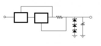
Reverting to our starting point, here is the original shunt circuit.
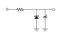
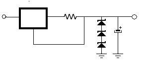
Since we want our shunt regulator to be practical and drop 6 to 10 volts, substituting a Constant Current Source (or CCS) will allow a controlled amount of current through the circuit while having high AC resistance.
This circuit uses the 10M45 CCS to good effect.
It has a 100K ohm Z or more impedance and is very simple with only the 10M45 and a sense resistor.

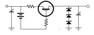
Here is another Very Simple Circuit, this time using a battery and a FET.
The gate of the FET is in the mega ohm range, so the battery life is almost the shelf life of the battery.

We can go upscale on complexity.
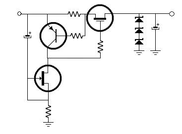
Here is the Shunt from Salas V1
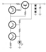
Here we are using a PNP transistor and a sense resistor to control The FET.
The 2NS170 wired as a CCS increases the gain of the PNP transistor.
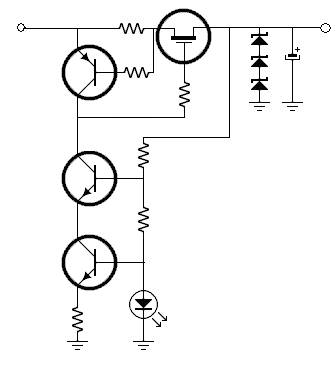
Here is the CSS from Salas V1.1
Uses 2 Blue or white 3V LED to get a stable 6V drop. I personally admire this. Not many parts.
This circuit looks like it should give good performance.
The original is in the DIYaudio thread simplistic-salas-low-voltage-shunt-regulator, post 501.
http://www.diyaudio.com/forums/powe...w-voltage-shunt-regulator-51.html#post1855189

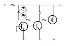
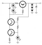
And here is the more complex Salas V1.2 regulator CCS.
Salas went back to the more repeatable Voltage of a PNP reference and improved the CCS of the PNP reference with a cascode CCS.
To look at the original, see http://www.diyaudio.com/forums/powe...-voltage-shunt-regulator-190.html#post2103465
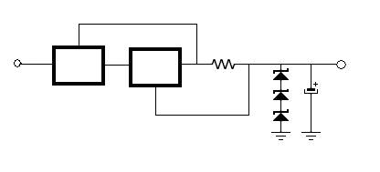
While we are on the subject of cascodes, if we are willing to drop more voltage, we can cascode the series elements for higher performance.
Here is an example of a cascoded 10M45. The result is impedance measured in 10’s of Mega ohms, rather than the ones of Mega Ohms for a single device.
The down side is the minimum voltage drop is increased. So for an 18V supply, this might need 28V in rather that about 24V in for the non-cascode version.
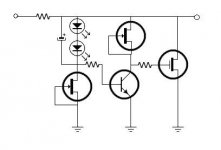
This circuit was mentioned in the Salas Simplistic Shunt Regulator thread. Substituting the LED string for the PNP as a voltage reference has tradeoffs.
The Tradeoff is that LEDs vary a lot in their voltage by depending on the color, and manufacturing process.
So the current sense resistor needs to be tuned to get the correct current, but the voltage reference is more stable with LED voltage reference.

http://www.diyaudio.com/wiki/Shunt Regulation Part 3
If we want more gain, we can substitute a JFET for the resistor. This is a copy of Salas V1 shunt element.
This looks to be a good compromise between complexity and gain. Note the feta are BL grade 2SK170 in order to draw 8 to 10 ma with low voltage drop.
The JFET must be able to operate at the low .7 voltage that being attached to the base of a transistor provides.
The original is in the DIYaudio thread simplistic-salas-low-voltage-shunt-regulator, post 501.
http://www.diyaudio.com/forums/powe...w-voltage-shunt-regulator-51.html#post1855189
Improvements for series elements:
So far, we have talked about the shunt element.
Lets go back and try to optimize the series element. Remember that the higher value the series resistor is, the more power it dissipates, and the higher voltage the raw supply needs to be.
Reverting to our starting point, here is the original shunt circuit.
Since we want our shunt regulator to be practical and drop 6 to 10 volts, substituting a Constant Current Source (or CCS) will allow a controlled amount of current through the circuit while having high AC resistance.
This circuit uses the 10M45 CCS to good effect.
It has a 100K ohm Z or more impedance and is very simple with only the 10M45 and a sense resistor.
Here is another Very Simple Circuit, this time using a battery and a FET.
The gate of the FET is in the mega ohm range, so the battery life is almost the shelf life of the battery.
We can go upscale on complexity.
Here is the Shunt from Salas V1
Here we are using a PNP transistor and a sense resistor to control The FET.
The 2NS170 wired as a CCS increases the gain of the PNP transistor.
Here is the CSS from Salas V1.1
Uses 2 Blue or white 3V LED to get a stable 6V drop. I personally admire this. Not many parts.
This circuit looks like it should give good performance.
The original is in the DIYaudio thread simplistic-salas-low-voltage-shunt-regulator, post 501.
http://www.diyaudio.com/forums/powe...w-voltage-shunt-regulator-51.html#post1855189
And here is the more complex Salas V1.2 regulator CCS.
Salas went back to the more repeatable Voltage of a PNP reference and improved the CCS of the PNP reference with a cascode CCS.
To look at the original, see http://www.diyaudio.com/forums/powe...-voltage-shunt-regulator-190.html#post2103465
While we are on the subject of cascodes, if we are willing to drop more voltage, we can cascode the series elements for higher performance.
Here is an example of a cascoded 10M45. The result is impedance measured in 10’s of Mega ohms, rather than the ones of Mega Ohms for a single device.
The down side is the minimum voltage drop is increased. So for an 18V supply, this might need 28V in rather that about 24V in for the non-cascode version.
This circuit was mentioned in the Salas Simplistic Shunt Regulator thread. Substituting the LED string for the PNP as a voltage reference has tradeoffs.
The Tradeoff is that LEDs vary a lot in their voltage by depending on the color, and manufacturing process.
So the current sense resistor needs to be tuned to get the correct current, but the voltage reference is more stable with LED voltage reference.
http://www.diyaudio.com/wiki/Shunt Regulation Part 3
Attachments
-
 ShuntReg022.jpg9.6 KB · Views: 3,639
 -
 ShuntReg026.jpg4.1 KB · Views: 3,513
 -
 ShuntReg028.jpg5.2 KB · Views: 3,521
 -
 ShuntReg030.jpg8.8 KB · Views: 3,520
 -
 ShuntReg032.jpg8.5 KB · Views: 3,489
 -
 ShuntReg034.jpg11.6 KB · Views: 3,075
 -
 ShuntReg036.jpg4.9 KB · Views: 3,057
 -
 ShuntReg038.jpg11.8 KB · Views: 3,082
 -
 ShuntReg024.jpg10.7 KB · Views: 3,063
 -
 ShuntReg004.jpg2.3 KB · Views: 3,092
Last edited:
Nice Wiki. Clean step by step schematics. Sometimes you mention blue and white LEDS. Only Red, Green, Yellow or Infrared please, since all others are noisy.
I have a question (pertinent)... why do we need more gain between the voltage reference and the output mosfet ?
Shunt Regulation Part 1
There doesn't appear to be a working link to the first installment. Does the page still exist? Thnx.
There doesn't appear to be a working link to the first installment. Does the page still exist? Thnx.
- Status
- Not open for further replies.
- Home
- diyaudio.com Wiki
- Shunt Regulation Part 2