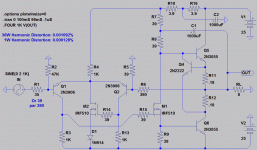
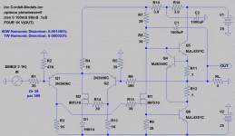
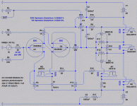
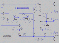
You are probably looking at PSRR sim with 10KHz and 15KHz injected to the rails.
Was done to see how much reached the output. Set power supplies back to 25VDC.


I've found the main weakness in my circuit to be the current
steering transistor. My earlier choice 2n3019 was just terrible
in this application. Especially when top thieving was applied.
Something about JLH's excess of bias through the middle had
a synergy with the non-linearity of this component that I did
not previously appreciate. I saw it only as a waste of 50W...
Replacement with MOSFET current steering transistor here
shows a preference for top thieving the original BJT did not!
The distortion now seems to be absurdly low. More so than
the increase in open loop gain would lead me to expect...
What the heck is going here that appears to work so well
with these same crummy old output and thieving devices?
Have I stumbled upon another synergy of non-linearities?
The second MOSFET is tackling a phase shift problem that
Elvee observed with VBE cap in my earlier offset correction.
Q2 behaves truer to intended purpose, a unity gain follower
with emitter current and collector voltage held constant as
close as possible to Q1's quiescent state. Or so I hope...
Attachments
I've found the main weakness in my circuit to be the current...
Hi Kenpeter,
I am impressed.
What current flows through R7, 8?
Is it not too high? or is it necessary to the circuit to work so well?
I like that one very much.
I would go so far as to say this is the most significant and valuable evolution of the JLH since the original version: both improvements make a huge difference, yet they are simple and neat.
Excellent!
One thing puzzles me: is the modulation of the R10 R4 node by the output through R7 intentional?
I would go so far as to say this is the most significant and valuable evolution of the JLH since the original version: both improvements make a huge difference, yet they are simple and neat.
Excellent!
One thing puzzles me: is the modulation of the R10 R4 node by the output through R7 intentional?
OK, I get it, it keeps constant the current through R4.One thing puzzles me: is the modulation of the R10 R4 node by the output through R7 intentional?
very interesting observations mentioned about post #9 and #10.
Unfortunately in the moment I haven't my CAD software on my computer, but if I have installed that, I will investigate that more exactly.
In general, I want to have three or four evaluation amps, in which I can (de)activiated (switch off/on) various topologies while listening sessions, so that I have virtual ten times more different amplifier concepts.
Untit this day I haven't find such a solution by others, OTOH without such a solution only measurement results are present for comparing, but no relationship between measuring results and listening results.
Last edited:
Hi Kenpeter,
I am impressed.
What current flows through R7, 8?
Is it not too high? or is it necessary to the circuit to work so well?
About 275mA. Just enough to cover the peak drive needed for 8 ohm load.
But could also be considered as a 43ohm RC Zobel. An open output would
always see at least this much load. And maybe that's part of the magic?
275mA is nowhere near enough drive for 4 ohm loaded 2n3055 outputs.
For 4 ohms, you could increase bootstrap currents further, but quickly
becomes absurd. As much as 30% of the output power wasted thusly.
Power supply and heatsink upcost in such a wasteful circuit have to
be considered. Better to spend the dollar on modern output transistor
with less beta droop.
Last edited:
Member
Joined 2009
Paid Member
I've found the main weakness in my circuit to be the current
steering transistor. My earlier choice 2n3019 was just terrible
in this application. Especially when top thieving was applied.
Replacement with MOSFET current steering transistor here
shows a preference for top thieving the original BJT did not!
The distortion now seems to be absurdly low.
The 2N3055 is famous for beta-droop and this places a bit of a load on the drivers, including your steering transistor. Perhaps the MOSFET provides better isolation between the output power devices and the input stage.
It must isolate better, its not gain, consider the open loop gain scenario.
There can be little increase in unity follower gain driving Q6's base, and
any further gains into Q5 are largely sabotaged by the thieving shunt.
Where is the ultra low closed loop distortion coming from then?
I think we got rid of the Early effect might be the biggest contributor?
And not too worried that a non-linear drain capacitance issue will take
its place, we have at least 5VDS at all times if this sim is to believe....
I want more of course, but my attempts to raise this minimum have so
far worked to make things slightly worse... Adding diode in series with
Q5's base for example should raise the drain minimum, and it does....
But the effect is not good. The open loop gain is unchanged here too,
but you can see how much the presence or absence of such a trivial
non-linearity might ruin perfect cancellation of the overall distortion.
I worry now, if I replace 2n3055 with something better like 2n5200,
would this completely screw the magic? What is cancelling what?
I need to dig up that spice model and try...
Last edited:
Looks like 4 ohms wants only bigger supplies and better transistors.
The bootstrap network needs no upgrade. No significant adjustments
except current sensing resistor values for higher output quiescent.
MJE340 is a slight performance downgrade from 2n2222, but has
a hole for mounting to output heatsink. I prefer thieving threshold
feel the heat, and reduce quiescent as output temperature rises.
I may revisit this choice later, it certainly doesn't require a high
voltage transistor. I was only after the hole, and the model was
there in Bob's library. Lazy selection happened...
There's no Cordell Model for IRF510, default .model might be suspect.
I can't help but distrust this distortion seems too low to be realistic.
Attachments
Last edited:
Back to 8 ohm quiescent for a second....
I wanted to observe how thieving can force a match between
seriously different transistors. Attempting 2n3055 with MJL4281A
Junk Transistor on top: 30W Harmonic Distortion: 0.003684%
Junk Transistor on bottom: 30W Harmonic Distortion: 0.002456%
If I had a mismatched pair, I'd still put the better transistor on the
bottom, it has to carry bit more current due emitter facing the rail.
I can't quite get Mosfet on the top to work anymore, but used to.
Wanted to show that for laughs, but not going to happen today.
Not sure what I changed that made that combo quit working?
There's enough bootstrap voltage, it should have worked...
Mosfet on the bottom always has issue when the output would
swing below the gate threshold. Would not expect that to work.
Only on the topside, together with thieving makes an Aleph Pair....
Last edited:
If this were a layout for single sided PCB, how awful would it be?
I'm not sure I have the best plan in mind for the grounding...
If I were to point to point Manhattan style over a ground plane,
might not matter. But I'd want a PCB sooner or later... Would
grounding the flipside of a double-sided PCB be enough?
Where about should signal and other grounds come together?
---------------
Pay no mind the Schottky diodes, just an option for class AB.
Linear Class A does not require anyone to install those parts.
----------------
Aw crud... I drew pinouts backwards for 2n3906! was looking
at spec sheet with pinout view from underneath. I could just
flip EBC with layout as-is. But the idea I had in mind was to
clip them face to face in a TO5 heatsink. Won't work as drawn...
Attachments
Last edited:
So, I have plenty of parts already around here somewhere.
But pain to find where have I stashed them all? So I went
shopping Tanner's, inventory better organized than at home.
Joy of re-buying stuff I already have and probably don't need.
I wanted 2n3055's in a flat TO3P type package, I'm sure
the ones I have hidden from myself were in metal cans....
So I get there, and lo and behold, he's got Fairchild 2sc5200!
in both TO220 and whatever the next one bigger than TO3P.
I get plenty of the NPNs for the JLH, and a few compliments
for other projects.
As for thieving driver, I have MJE340 somewhere. But Tanner
had BD139 and BD140 fullpacks with higher beta. Already
thinking MJE340 VCEmax was overkill. Thieving happens at
1.4VCE. I would rather select for the greater beta, thanks...
Found IRF510, no need to substitute this one...
I probably bought bigger resistors than needed for ease
of handling. I decided gate stoppers ought to be carbon,
but the rest should be metal types... The bootstrap pair
I selected 5W wire wound, as these will get plenty hot.
Single sided copper PCB. I got some pre-made islands for
Manhattan prototyping somewhere. If I can't find them in
due time, I got plenty of scrap pcb I can cut up to make
islands... Not talking any huge quantity needed.
I'm sure I saw my stash of Schottkys around here recently?
I'll will surely need them for square law Class A, as my 24V
6A switching supplies would be undersized for stereo with
no cheats. I could only manage no cheats in mono for now.
My 2n3906's are with the Schottkys, I'm sure of it. Maybe
in box under pinball machine? (Williams Black Knight 1980)
I don't have micas or pads for the big transistors. I would
have to cut up some old TO3 style micas? Even those may
not fully cover the back. Maybe I ask the parts guy at work
to get me some thermal pads tacked onto our next order...
R2D2 was in the parking lot? No seriously! They had some
robot group happening, it was weird. The cool sorta weird.
I got my 10cent (fedex included) TTL data books from TI
today, also a pair of MSP430 launchpads at $4.30 each.
I was amazed they included the usb cable and extra chip
and some resistor SIPs, but failed bigtime to include any
CD of the software. Guess I have to download...
Last edited:
Seriously need to charge up my good camera.
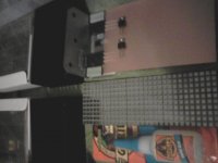
This here blur of what might become an amp...
See the sheet of Manhattan islands ready to
break away and glue over the ground plane?
Wish I knew where to get more. Something I
bought at a HAM convention, but forgot who
it was that sold them...
Not sure I care to use those Simpson ties.
Cheaper and stronger than aluminum, but
will they move the heat? Can't be worse
than the grey pad that goes between....
Could bolt straight to this heatsink, but
then gotta make fixtures for transistor
legs to screw into the PCB somehow.
I got a flat bar of aluminum round here
somewhere. Not sure if its a shape that
would be any help.... I want like an L....
Power supplies in the background only
rated for 4.2Amps . Linear Class A not
an option, thus the Schottky pairs for
Square law vs Square law Class A.
I can power for Linear Class A at work
on big Agilent supplies, but not at home.
Make it so the board can shunt regulate
for either curve on demand...
Attachments
Last edited:
Member
Joined 2009
Paid Member
I'm looking forward to some reports on this one, my JLH 10W class A is still half-built, 2N3055's of course and with the design now looking old fashioned compared with where this thread is heading 😀
Member
Joined 2009
Paid Member
Drilled holes in one steel L bracket; is that news?any news ?
I am still puzzling over simple mechanical details.
Lamer of the century award...
If I sandwich the output transistors between the
L and the copper backside of my board (maximum
heat dissipation), I might want to flip the pinout on
my layout. Else I have to build the whole circuit on
the backside. I don't know how well the islands will
stick to the copper side? I was planing to superglue
the bare side of my Mahattan pads to the bare side
of the board. I've seen it done on the copper side,
but I don't know if attachment is sturdy like that..
-----
No, I just need to drill holes to let the output legs
feed through the board to the bare side, without
touching the groundplane as they pass through...
BD139 fullpack isn't same thickness as 2SC5200.
How do I shim the sandwich to insure it touches
the L bracket of the heatsink? Or is just sticking
it between groundplane and L bracket adequate?
Only needs to sense output heat, not dissipate
much of its own...
Last edited:
- Status
- Not open for further replies.
- Home
- Amplifiers
- Solid State
- Shunt Regulated JLH
