Core losses are frequency dependance, the higher the frequency the more eddy currents, that’s why amorphous and nanocrystalline are popular (mostly used for power supplies) because they have really thin laminations 18μm-22μm.
For SiFe, thinner laminations have less permeabilty and more constant permeability. A 0,05mm SiFe core has almost flat permeabilty (μr about 1000) up to 10kHz but also a lot lower permeabilty then 0,3mm. The 0,3mm starts from 20.000 (dependable about the quality of the core) but drops very, very fast after hundred Hz.
Btw Gorgon53 says: “ 0,5mm has usually higher losses and less permeability” .
Maybe he has right, maybe not. The dc permeability of 0,5mm is higher then 0,3mm but at 50/60Hz there could be so much eddy currents already that permeability is already lower at that those frequencies.
Last edited:

Actually, in an opt, iron losses decrease with increasing frequency because induction goes down and at some point the eddy current losses in the coil will take over. At this point the core is practically decoupled from the coil and can be ignored
True, but it’s hard to point a finger on when low eddy current is low enough. I prefer the lowest although not at any cost.
Last edited:
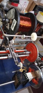
Nice work! Are one of these hand cranked India-made semi-automatic feeder machines? I was tempted to buy one for demonstration and teaching purposes.
FWIW-Nice thread... How important is the laminate thickness ? Is it absolutely necessary to use 0.3mm laminate or If i need to work with 0.5mm, what parameters do i need to take into consideration? I do understand in yesteryears most OPTs were made up of regular iron cores and not too thin,but still achieved good bandwidth...
ChiFi unit 350 watt (114 wide x 65 thick mm) I'm rewinding shown in previous post pics, has laminates of .015", They are soft...
US made 630 watt (114 wide x 82 thick mm) laminates are .025"... They are noticeably more rigid- more than just the increase in thickness- imo...
Remarkably similar to a lathe..ei output for f2a pushpull
View attachment 1170256
Do you have a tension spec- Ft/lbs or N/M you observe while winding?
Also, does that figure vary as distance from the core?
Jim
Some random pictures of my winding setup. A manual rotation and semi feeding mechanicsm.. The feeder works pretty good, Not as accurate as servo motor microprocessor controlled,but very durable and with patient winding,does the job nice


Attachments
A friend made this, for 2 300B, PSE or PP, 2 anode load impedances and CFB.

Well done! Clean design!
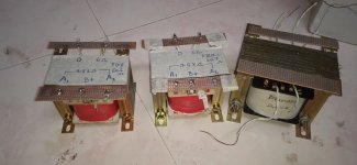
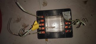
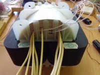
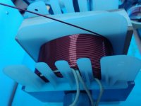
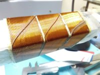
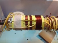
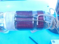
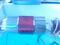
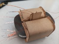
Sharing some kinky stuff from 2017, where I started learning and experimenting with too many things at once. Photo 4 is a vertically sectioned interstage transformer. Photos 1,2 and 3 represent heater transformer windings with many voltages. Photos 5 and 6 are depicting a power supply transformer for tube amplifier, with HT and heater voltages.
Sharing some kinky stuff from 2017, where I started learning and experimenting with too many things at once. Photo 4 is a vertically sectioned interstage transformer. Photos 1,2 and 3 represent heater transformer windings with many voltages. Photos 5 and 6 are depicting a power supply transformer for tube amplifier, with HT and heater voltages.
Attachments
Some random pictures of my winding setup. A manual rotation and semi feeding mechanicsm.. The feeder works pretty good, Not as accurate as servo motor microprocessor controlled,but very durable and with patient winding,does the job nice
tnvijay, pl post more details of the output transformers you wound...assume those were for the baby Huey el84 amp.
core size, winding details...
It seems that cores has higher relative permeability? Judging by the huge LpHere is finished transformer, 60W PP, 33%UL, 12%CFB, 1165H primary inductance @200V/50Hz, 3.28mH leakage inductance, 67KHz -3dB top frequency, primary R=67.5 Ohm, CFB R=7.7 Ohm, Secondary R<=0.2 Ohm. I tested it in Williamson and HK Citation II circuits, both are known to be quite demanding to the quality of output iron. Frequency response of the last is flat up to 50KHz, as with original output iron.
Bobbin laser cut from 2mm composite epoxy laminate, sheet material is cemented before cutting. Design of the bobbin is universal, it can be manufactured with laser, CNC mill (with corner clearance for 3.175mm mill), or 3D printed.
@gordon53 - bobbin from China is not expensive, shipping is very costly because of dimensions. As per link of oemcar, 7.5 Euro bobbin price, 25.98 Euro shipping cost (for 1 bobbin). For 2 bobbins everything is even worse - can't be shipped to Europe by China Post, so DHL transport is 94.86 Euro.
What Bdc has to do with L ?@AndreK the formula is correct and Bdc will increase if more turns. If you increase the turns also L will increase. L is proportional to square number of turns.
Think about it, Simple example:
You have your power trasformer, you connect your primery to 120VDC instead of 120VAC, what happens to your transformer, though the L and T is still the same?
Bdc is proportional to AmpTurns, concidering the core is still the same, so the lager current and/or the more turns, the higher Bdc. L is for calculation of Bac at specified frequency.
Any comments?
Last edited:
Don't get me wrong, Bac also depends of AmpsTurns, but with the AC, the current will be different, thats where L comes to its role. In this care the current depends on the combined impedance of the inductor, including R and X (I am not getting into the vector agebra). R is a pure DC resistance, X=2*3,14*f*L.
R in Ohms, f in Hz, L in Henry. X is in Ohms.
R in Ohms, f in Hz, L in Henry. X is in Ohms.
- Home
- Amplifiers
- Tubes / Valves
- Show your transformer work (gallery)