Did you go further in the thread to see some of the measurements that were posted?
synergy.....Take #7
synergy.....Take #7
Simulations show rollback improves "things" quite a bit. I've got no idea how much of a difference that is while listening and that is why I suggest at least the > 90 deg rollback with generous radius to get to a meaningful territory also in the listening side of things 🙂
After all these are complicated devices to build from ply so I would fabricate what ever rollback and accept the device won't be perfect and be happy with it. After all the flat sided part is not the best profile, a continuous curvature works better (experimenting with the ATH will reveal this). This is the easiest way to build MEH at home so it is just a compromise between the cost and performance and should be appreciated as such. If there still is desire to go further with the performance consider CNC machined waveguide so that the whole device can be optimized.
After all these are complicated devices to build from ply so I would fabricate what ever rollback and accept the device won't be perfect and be happy with it. After all the flat sided part is not the best profile, a continuous curvature works better (experimenting with the ATH will reveal this). This is the easiest way to build MEH at home so it is just a compromise between the cost and performance and should be appreciated as such. If there still is desire to go further with the performance consider CNC machined waveguide so that the whole device can be optimized.
Last edited:
fluid, I don't see anything there to demonstrate what you said. I have no idea what you're talking about.
...
I am not quite following. If we are to believe the simulations, it appears that there is significant influence of the interface between the (conical) compression driver exit and (even matching) throat angle of the horn/wave-guide. Although the interface appears to be "smooth" there is significant first derivative difference.
Now taking the argument further, why would the discontinuity at the abrupt change of flare, and consequent first derivative, further from the throat be different? Should a tangential interface not be better?
...
With the some hours of experimenting with the ATH shows that it is quite difficult to optimize a waveguide when there is the conical exit section in the driver. The throat section is quite small though so problems there affect performance mostly above 10kHz which in comparison to the problems with poor mouth termination feel insignificant to me. Mouth first, then throat if there is need to rank the importance. Optimizing both would be best of course 🙂 But again, one can purchase driver without conical exit and design a "perfect" waveguide for it and get it manufactured to precision. Ability to build a MEH in garage with circular saw for the driver already purchased is just a compromise to that, and a nice one. Some kind of mouth rollback would be and improvement making it worthwhile to pursue.
Last edited:
That would make two of us then, I have no idea what you don't understand or what you are wanting to see, which makes it hard to provide it. I've tried my best, if you can explain what you want then maybe I can help.fluid, I don't see anything there to demonstrate what you said. I have no idea what you're talking about.
Matching a conical exit driver to an OS throat causes an abrupt change of curvature very close to the throat where it matters most. This is quite different to what happens much further out when there is a change of angle from the secondary flare. The two things are not equivalent.I am not quite following. If we are to believe the simulations, it appears that there is significant influence of the interface between the (conical) compression driver exit and (even matching) throat angle of the horn/wave-guide. Although the interface appears to be "smooth" there is significant first derivative difference.
Not sure what you mean by tangential interface.Now taking the argument further, why would the discontinuity at the abrupt change of flare, and consequent first derivative, further from the throat be different? Should a tangential interface not be better?
Diffraction is easy enough to measure but the perception of it is not quite so obvious. There are many differences between the different Danley models which could easily swamp the effects of different flares.However, it seems to me that we are contemplating something that may have a second of higher order of influence, both regarding measured effect and perceived one. After all, does anyone ever reported perceived difference between Danley's Unity with abrupt change between the first and second flare and a gradual one?
It is easy enough to simulate and measure something that would perform objectively better but it is no simple task to make one.
Here's a start
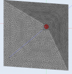
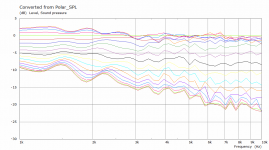
This is a basic 50x50 conical Horn 200mm Deep, driven by a flat diaphragm of 25.4mm cut into a 25.4mm square. As close as I can get to Rob's initial horn without knowing the depth.
This is in an infinite baffle so there is no real termination issue from the baffle itself. There are no taps just the straight CD to keep it simple.

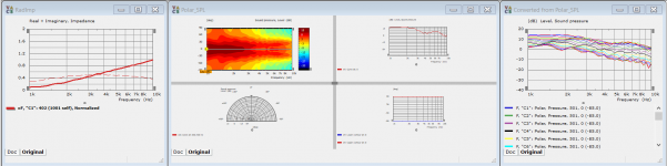
The Spectrum results are attached below.
You can see the Difference in Radiation Impedance to an OS Horn, the polar is not normalized and in general it looks messy in comparison to the best that can be achieved, but I have seen much worse.
This is a basic 50x50 conical Horn 200mm Deep, driven by a flat diaphragm of 25.4mm cut into a 25.4mm square. As close as I can get to Rob's initial horn without knowing the depth.
This is in an infinite baffle so there is no real termination issue from the baffle itself. There are no taps just the straight CD to keep it simple.
The Spectrum results are attached below.
You can see the Difference in Radiation Impedance to an OS Horn, the polar is not normalized and in general it looks messy in comparison to the best that can be achieved, but I have seen much worse.
Attachments
Hi fluid,
I have accepted that the simulations show that the abrupt change of curvature at the throat matters. But, I have not seen any simulation or explanation why it should matter more than elsewhere. Could you provide a reference, please?
Sorry for the poor language. What I meant to say is that to prevent an abrupt change - like a change from one angle to another as in Rob's and others' implementations, a curve that meets the first flare at a tangent would alleviate the abrupt change.
Exactly my point.
On a different note, how does one quote so that the name of the person is included?
Kindest regards,
M
Matching a conical exit driver to an OS throat causes an abrupt change of curvature very close to the throat where it matters most. This is quite different to what happens much further out when there is a change of angle from the secondary flare. The two things are not equivalent.
I have accepted that the simulations show that the abrupt change of curvature at the throat matters. But, I have not seen any simulation or explanation why it should matter more than elsewhere. Could you provide a reference, please?
Not sure what you mean by tangential interface.
Sorry for the poor language. What I meant to say is that to prevent an abrupt change - like a change from one angle to another as in Rob's and others' implementations, a curve that meets the first flare at a tangent would alleviate the abrupt change.
Diffraction is easy enough to measure but the perception of it is not quite so obvious.
Exactly my point.
On a different note, how does one quote so that the name of the person is included?
Kindest regards,
M
In basic terms the distances at the throat are small and changes there will affect higher frequencies more where diffraction is a bigger concern. As you move down the guide to the mouth the dimensions get larger which tends to move the effects seen lower in frequency.I have accepted that the simulations show that the abrupt change of curvature at the throat matters. But, I have not seen any simulation or explanation why it should matter more than elsewhere. Could you provide a reference, please?
Maybe this paper from Don Keele offers something
http://www.xlrtechs.com/dbkeele.com/PDF/Keele%20(1973-09%20AES%20Preprint)%20-%20Optimum%20Horn%20Mouth%20Size.pdf
My comments on the secondary flare relate specifically to the use of of a conical horn like seen in the simulation above. Given the ripple and general mess when terminated by an infinite baffle an angled or curved secondary isn't going to undo that but it can have a beneficial effect on the polar response as shown by Don Keele a long time ago.
http://www.xlrtechs.com/dbkeele.com/PDF/Keele%20(1975-05%20AES%20Preprint)%20-%20Whats%20So%20Sacred%20Exp%20Horns.pdf
On a different note, how does one quote so that the name of the person is included?
That is easier to answer 😉 Just copy the QUOTE= line and paste it as many times as you want, just remember to add the end quote tag in between.
Code:
[QUOTE="mefistofelez, post: 6518256, member: 1497"]Hi fluid,
Ah, that makes sense. Interesting how our assumptions lead to miscommunication. What I was referring to was an OS wave-guide, well matched at the CD to throat interface, but without any secondary flare termination.
Kindest regards,
M
fluid said:My comments on the secondary flare relate specifically to the use of of a conical horn like seen in the simulation above. Given the ripple and general mess when terminated by an infinite baffle an angled or curved secondary isn't going to undo that but it can have a beneficial effect on the polar response as shown by Don Keele a long time ago.
Ah, that makes sense. Interesting how our assumptions lead to miscommunication. What I was referring to was an OS wave-guide, well matched at the CD to throat interface, but without any secondary flare termination.
Kindest regards,
M
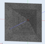
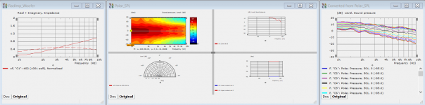
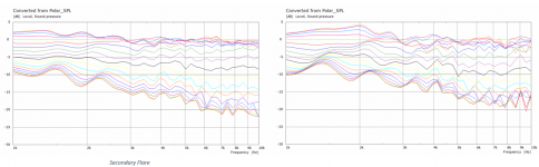
Here is what happens when you add a secondary flare at 30 deg to the main horn. Everything gets better 🙂
I hope this is some use to someone because the sim time went from 35 mins to 10 hours 😱

This is still with an infinite baffle at the edge of the second flare but it shows that it already does a pretty good job of cleaning up the majority of polar issues but does nothing for the very close on axis results. Normalized to 20 degrees looks better

This is why I said before that adding a 36 to 50mm roundover on the edge would be a reasonable way to terminate the baffle in real life and get closer to the ideal infinite baffle case for diffraction control.
I hope this is some use to someone because the sim time went from 35 mins to 10 hours 😱
This is still with an infinite baffle at the edge of the second flare but it shows that it already does a pretty good job of cleaning up the majority of polar issues but does nothing for the very close on axis results. Normalized to 20 degrees looks better
This is why I said before that adding a 36 to 50mm roundover on the edge would be a reasonable way to terminate the baffle in real life and get closer to the ideal infinite baffle case for diffraction control.
Attachments
Last edited:
Allen you edited your post but I already had this written, maybe it helps understand it better
Here is a side by side comparison when both are normalised to 20 degrees

The diffraction is better but the secondary flare is mainly affecting polar control. The bulk of the diffraction has already happened in the horn without secondary. Both of these are terminated in an infinite baffle so the difference is in how the shallower angle of the secondary gives a better termination.What is happening with the diffraction in this case, you are just saying is that it is better?
Given the short distance and the existing diffraction in the conical horn I don't think a smoother curve from horn to baffle will be much more effective than a straight secondary with a roundover added afterwards given that constructing it is considerably more difficult.You said before that the secondary flare might be no different to the tractrix.
Here is a side by side comparison when both are normalised to 20 degrees
Attachments
The reason I posted this question was due to me looking into this post on another forum
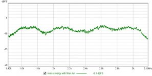
I zoomed into measurements of my horns to find a ~400Hz ripple that calculated very closely to the throat to mouth distance. It's only plus/minus ~1dB but it's definitely there.. Whether I can hear it I have no idea...
I'm going to start a very slow project to rebuild my horns. I will let you know how they measure around Halloween 😀
Cheers,
Rob.
Attachments
Reflections like those shown in the linked post (which is a good article in post form) are from the termination. The smoother you make it the better it is. When you say rebuild your horns what do you have in mind?
I'm planning to rebuild my current MEH's with a curved section instead of the stepped version that I currently have. I'll also add a round over to the cabinet edges. I'm testing midbass cabs as well so the tops may get slightly larger to match them. (my MEH's are only 2 way so crossover to midbass cabs ~280Hz)
Thanks,
Rob.
Thanks,
Rob.
- Home
- Loudspeakers
- Multi-Way
- Should there be a certain type of curve ? MEH Q ?