OK all, The schematic has arrived. Here is a link to the relevant section.
http://www.diyaudio.com/forums/gallery/uploads/326191/2015-02-06_19_31_29.jpg
the 60 uf cap is first in line off of pin 8 on the rectifier tube. the 50 uf/25v cap is used for the 6bq5 tubes which are the output tubes? so, given this new info, any ideas? I tried searching for a 60uf 450 v cap and cant find much. I found a 47 uf 450 V, which should work for the 40uf, and there is an 80/450, but that seems to be the closest I can get to the 60/450.
thoughts?
pair of 33 mfd capacitors will also work. a few cents cheaper.
+1 for famousmockingbird
You obviously didn't understand my point, so I will clarify. The tolerance of the CE manufacturing can caps are -10%, +50%. Fifty percent is a large value, so like I said exact capacitance isn't necessary.
I would also like to say that if I can get better performance for much cheaper (not a few cents as Mike567 so seems to think) then it's a no brainer. For gods sake I wasn't telling him not to buy the darn thing, I was just letting him know there are other options.
And for the record one would save much more than a few cents in this situation.
+1 Mike567
OK. I unsoldered the cap can from the amp today. Took my trusty dremel tool and cut one end off of it to see what was inside. Not exactly what I was expecting. It was just a big core of tightly wound foil with a paper backing. I guess the leads from the solder pins were placed at various depths within the coil of foil/paper to determine the capacitance values?? I guess the one thing I dont understand is how 3 of the values were 450v and one was 25v if all the leads were in the same coil??
Anyway, looks like time for some new individual caps I think. A few questions.
1. Should I get radial or axial? Or does it matter? Is it just a preference for soldering them together to the other components, i.e. whatever makes it easier?
2. There was a common ground on the cap can. What will I use to replace that common ground now?
Thanks in advance for your replies!
Hi brandoh73,
Did the schematics come with a layout diagram? If yes please upload it along with some high resolution photos, and maybe upload the whole schematic while your at it. There is an attachments section under "go advanced" you can use to upload everything to this site🙂
Did the schematics come with a layout diagram? If yes please upload it along with some high resolution photos, and maybe upload the whole schematic while your at it. There is an attachments section under "go advanced" you can use to upload everything to this site🙂
I have attached the schematics and layout diagram. They are in one PDF file. The person I got this from has a small business selling these things, so I redacted the amp model number info. But everything else is there. Let me know if the resolution is good enough. I had to scan it at a lower res because the forum said the original file was too big.
Attachments
5Y3 datasheet says 20uF for reservoir capacitor and in the schematic the value is 60uF, I wouldn't go with anything higher than 47uF for the sake of the rectifier.
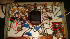
From what I can see you have tons of room and a tag board that the dropping resistors are mounted to that you can use to solder the new caps to.
Order two of these: TVX2W470MDD Nichicon | Mouser
Solder the positive leads directly to "A" and "B" and the negative to ground
Buy one of these: TVX2W220MCD Nichicon | Mouser
Solder the positive lead directly to "C" and the negative to ground
Buy one of these: TVX1H470MAD Nichicon | Mouser
Solder it across R7 where "D" is in the picture making sure the negative side is on the ground side of R7.
Where you choose to put the grounds for the power supply caps could help with ground loops. I would maybe put "A" and "B" at the power transformer center tap ground and put "C" to where the input is grounded.
Happy soldering🙂
Attachments
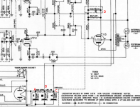
Yes, the 60 μF. 1st filter cap. value is highly abusive of the 5Y3 rectifier. Even 47 μF. is pressing your luck. There are several ways to deal with the problem. A method that will not increase the PSU ripple level is to swap the 5Y3 out and install a Sovtek 5AR4 in its place. To make 100% certain that things are safe, insert a CL-130 inrush current limiting thermistor in the line between pin 8 of the rectifier socket and the 1st (60 μF.) filter capacitor. As the forward drop in a 5AR4 is considerably smaller than that in a 5Y3, the value of the resistance between the 1st filter cap. and the reservoir (2nd) cap. has to rise.
Cheap units of the time frame this amp was made all too often ignored published data. Frequent replacement of the rectifier was the customer's problem, while engineering a proper PSU would have interfered with profits. The phenomenon has been around for a very long time, is currently around, and there's absolutely no reason to believe that it will not be present, in the future. 😡
Cheap units of the time frame this amp was made all too often ignored published data. Frequent replacement of the rectifier was the customer's problem, while engineering a proper PSU would have interfered with profits. The phenomenon has been around for a very long time, is currently around, and there's absolutely no reason to believe that it will not be present, in the future. 😡
Interesting observations. The 5y3 tube appears to still be functional. No idea how old it is though. I have caps on order, I have an extra 40uf cap, I will use that in place of the 60uf (I ordered 68uf, but that appears to be too much now). Thanks for the info everyone!
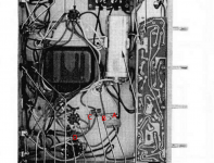
OK. I have the caps in house. Famousmokingbird, would you be so kind as to provide more guidance as to where to ground the caps to? I have attached an image of the bottom of the amp. There were 2 ground wires attached to the original can cap. I put red arrows with circles on them at the origin points of those ground wires in the image. the one on the right comes off a post between the "B" RCA input for the tuner and phono input. The one on the left comes off of a ground lug on the bottom of the 5y3 tube socket.
So is the one on the left, on the tube socket, already a ground? and the wire was providing a ground point for the cap can? If so is it just sufficient to ground everything to that wire, including the lead from the RCA input?
Or do I need to find a new ground point for everything, including the existing ground leads mentioned above?
Sorry to ask what may be dumb questions. I am still learning this stuff. Any help is greatly appreciated!
Attachments

Yikes! No wonder you have 60Hz hum. I'd completely rewire the tube heaters. Twisted pairs, run along the perimeters of the chassis, or at least crossing signal wires at right angles. Maybe buy Morgan Jone's book for more detailed info (or similar posts here, if some can be recommended). He also covers the grounding principles. Given the look of that thing, I doubt much care was taken in any aspect of the wiring layout.
Sheldon
Sheldon
Last edited:
Yikes indeed!
If you have the time and inclination, I would rewire the lot rather more neatly. (It could hardly be more untidy - sorry!)
Not to mix you up entirely, but I would allocate the power capacitors' values a little differently. Where your schematic shows, left-right, 60 - 40 - 20µF, I would put 20 - 60 - 40µF instead respectively. The 120Hz ripple should remain reasonably low, while the highest value should actually be on the output tube's h.t., i.e. the 60µF where the 40µF is at present.
And Brandoh73 (sorry to be in advising mode) - there are hardly ever such things as stupid questions. Don't apologise. Believe me, we ALL came thataway. Today I am a retired professional EE , but in early years it took me weeks to understand the difference between voltage and current ..... Only smart-***** 'start' at the top (or so they think).
If you have the time and inclination, I would rewire the lot rather more neatly. (It could hardly be more untidy - sorry!)
Not to mix you up entirely, but I would allocate the power capacitors' values a little differently. Where your schematic shows, left-right, 60 - 40 - 20µF, I would put 20 - 60 - 40µF instead respectively. The 120Hz ripple should remain reasonably low, while the highest value should actually be on the output tube's h.t., i.e. the 60µF where the 40µF is at present.
And Brandoh73 (sorry to be in advising mode) - there are hardly ever such things as stupid questions. Don't apologise. Believe me, we ALL came thataway. Today I am a retired professional EE
, but in early years it took me weeks to understand the difference between voltage and current ..... Only smart-***** 'start' at the top (or so they think). Follow -
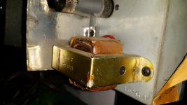
I don't see the original question having been answered! I could not open the picture in the opening post, but it is hardly ever necessary to replace a transformer unless it is open/shorted/burnt out, which condition can mostly be confirmed with a multimeter. It might sometims be necessary to replace damaged/corroded/perished leads, which can be done with careful attention and by observation. This especially when inside some sort of cover.
I don't see the original question having been answered! I could not open the picture in the opening post, but it is hardly ever necessary to replace a transformer unless it is open/shorted/burnt out, which condition can mostly be confirmed with a multimeter. It might sometims be necessary to replace damaged/corroded/perished leads, which can be done with careful attention and by observation. This especially when inside some sort of cover.
It is a bit untidy. It is 50 years old though, so I can forgive that a little bit. Thanks for the info on reordering the capacitors. I can definitely do that. But I still need some guidance as to how to ground all the caps. Any thoughts there?
Post #2, my first suspicion was heater wiring when you mentioned 60Hz hum. Rewiring at least the heater circuit should be your first priority if you want acceptable hum levels.
As for the power supply capacitors, I would ground "A" and "B" at the rectifier ground on the left, and "C" at the ground near the inputs. See attachment.
As for the power supply capacitors, I would ground "A" and "B" at the rectifier ground on the left, and "C" at the ground near the inputs. See attachment.
Attachments
Thanks all! I will start investigating how to rewire the heater circuit as well. But as always any assistance in that area is appreciated as well.
OK. the new caps are in. now things are weirder than before. First things first, there is no sound out of the left channel. Now I am not sure this can be contributed to the work I did with the caps or not. I took the front end of the amp apart this past weekend and cleaned all the pots/contacts so the controls would work more smoothly. I did not unhook anything to do that though.
There is also still hum coming from the one channel that works, but the hum disappears when I turn the bass level all the way up. trebel level has no effect on the hum. The overall level of hum with the bass mid way did seem to go down though.
So, first things first, would anything I did with the caps effect the left channel? If you look at the image from the previous post, the left channel would be the one driven by the tube on the right, which has the 25v cap on it. I guess if I somehow did not ground that one right that would cause that channel not to work?
- Status
- Not open for further replies.
- Home
- Amplifiers
- Tubes / Valves
- Should Output Transformers be replaced