I was referring to this image.
Yes, I realise now that we were talking about two different images! 👍

Impedance is just a piece in the puzzle, without the others it's pretty meaningless.
Yes, we can only deal with this random combination of drivers at a very simple, "let's see if it works", level.
it would be great if you drew a diagram
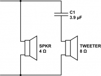
To be absolutely clear, you already have the basic diagram (see attachment).
The upper connection on both the woofer and tweeter should be the positive one.
And the nominal impedance of the arrangement shown in the diagram is 4 ohm.
Attachments
And at 15 bucks just for the tweeters I don't see the point - it's unlikely the midrange will be NOT a nasty mess. Any off-the shelf boom-thingy for the same money will probably beat it.Yes, we can only deal with this random combination of drivers at a very simple, "let's see if it works", level.
OTOH, if the OP were happy to hack together a simple measuring rig (midrange is easy-ish to measure, even with cheap electrets), find the T/S parameters of the woofers with another hacked-together rig, build an enclosure accordingly (spacing centers nice and tight), measure the whole thing in 5- or 10-degree steps in the crossover region, learn Vituixcad and feed it with those measurements, design and build a crossover, ...then it could actually be a pretty nice little gem!
Could be something for a rainy weekend?
the one in the cabinet, of course, which is connected to PAM8610 output.the 'input connector here' you mean the output on the pam8610 or my audio source ?
Just like in the diagram, period.so that means parallel wiring is ok? sorry for my question
YOU have already drawn the diagram in post #1 😱it would be great if you drew a diagram, it would help me understand your idea better
THAT. I only tried to put "all together" for better comprehension and also expanded a little on capacitor choice and why.JMF is not telling you anything different from what I have already shared with you.
But every new explanation is taken as independent and contradicting all earlier ones .....
Suggest you read and reread them until everything clicks in, we are all saying the same.
I guess you are quite an optimist 🙂OTOH, if the OP were happy to hack together a simple measuring rig (midrange is easy-ish to measure, even with cheap electrets), find the T/S parameters of the woofers with another hacked-together rig, build an enclosure accordingly (spacing centers nice and tight), measure the whole thing in 5- or 10-degree steps in the crossover region, learn Vituixcad and feed it with those measurements, design and build a crossover, ...then it could actually be a pretty nice little gem!
Could be something for a rainy weekend?
Given the OP questions I would keep it real simple, wire as in the first schematic using a 3.3uF bipolar cap and be done with it.
Why 3.3uF?
Because I am not SURE it´s a 4 ohm or an 8 ohm tweeter, so I "split the difference".
I have seen worse in Professionally/Commercially designed and built Sony/Aiwa/Panasonic/Sanyo mini component cabinets, those with an 8" woofer and up to 5 tweeters, using only capacitors as crossovers.
Everything in parallel, of course. 🙁
Last edited:
wow, thank you all for the support and the patience. I really want to get into this DIY audio area but didn't know where to start. any advice for a new guy like me. (i just know a little bit about circuit analysis) Thank allSuggest you read and reread them until everything clicks in, we are all saying the same.
Last edited:
where should I add the resistor and why is that?Don't forget the resistor.
You don't know whether the tweeter is too loud for the woofer. Maybe it is the other way around.
Thank you for the suggestion. if the tweeter was too loud maybe the resistor will be needed. Or maybe if I add a couple of passive radiators its the other way aroundYou don't know whether the tweeter is too loud for the woofer. Maybe it is the other way around.
@JMFahey, Sorry for asking again, but can you explain more specifically why, by wiring the woofer and the tweeter together parallely, I wouldn't get 2.67 ohms? Thank you.nominally in parallel, but typically at the highish crossover frequency, woofer won´t show 4 ohm impedance any more but a significantly higher one, so no big deal.
You have been given practical answers to solve a specific problem, this is not an online Electronics course nor we have time to answer 1000 (or 10000) questions , you should get an Electronics book and study it.
That said, I´ll answer this one but suggest if you want to learn besides solving this problem, take the bull by the horns and study.
1) they are not straight parallel connected, each of them has also a series element which adds up to each transducer impedance, so you do not have 4 or 8 ohms respectively but higher values.
Significantly higher.
2) starting with the easy one, the tweeter: it has nominal 8 ohms (won´t show the way more complex full equivalent because I don´t want to trigger a dozen new questions) in series with a capacitor, which adds its own impedance.
Nominal crossover frequency for 8 ohm and 3.3uF is 6kHz
Calculate it yourself: http://www.sengpielaudio.com/calculator-RCpad.htm
Which means that at 6kHz tweeter has 8 ohm, capacitor also 8 ohm, so nominal 16 ohm.
Go figure.
3) now to the woofer.
It ALSO has a series inductor, only not "outside" and easily visible but internal.
The inductor is the voice coil itself plus some mechanical resonances.
After all, the voice coil is made out of quite a few turns of copper (sometimes aluminum) wire, think 100-200 turns, wound around an iron core .... a full fledged inductor I would add.
No need to calculate impedance as with the tweeter, speaker manufacturers graciously provide an impedance curve on the datasheet.
I don´t have yours, but here is a typical one, yours will be same shape, and based on nominal 4 ohms, but this shows the concept:
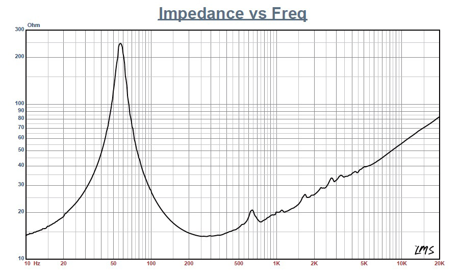
notice the STEEP upwards impedance rise above mere 500Hz, clearly behaving like a series inductor; and at 6 kHz (tweeter crossover frequency) this 16 ohm speaker shows a whopping 40 ohm impedance 😱
Scaling to your 4 ohm woofer, it might very well show some 10 ohm impedance there.
So at the 6kHz crossover frequency, the point where they would approach being in parallel, both are working just as hard there, we would have 10 ohm (woofer) in parallel with 16 ohm (tweeter) ... do the Math.
Below that crossover frequency, Tweeter is decoupled/separated by increasingly higher capacitor impedance, above it Woofer is decoupled, at no audio frequency you have resistive 4 ohm and 8 ohm in parallel.
Hope this answers your doubt.
PS: just build that cabinet!!! 😉
That said, I´ll answer this one but suggest if you want to learn besides solving this problem, take the bull by the horns and study.
1) they are not straight parallel connected, each of them has also a series element which adds up to each transducer impedance, so you do not have 4 or 8 ohms respectively but higher values.
Significantly higher.
2) starting with the easy one, the tweeter: it has nominal 8 ohms (won´t show the way more complex full equivalent because I don´t want to trigger a dozen new questions) in series with a capacitor, which adds its own impedance.
Nominal crossover frequency for 8 ohm and 3.3uF is 6kHz
Calculate it yourself: http://www.sengpielaudio.com/calculator-RCpad.htm
Which means that at 6kHz tweeter has 8 ohm, capacitor also 8 ohm, so nominal 16 ohm.
Go figure.
3) now to the woofer.
It ALSO has a series inductor, only not "outside" and easily visible but internal.
The inductor is the voice coil itself plus some mechanical resonances.
After all, the voice coil is made out of quite a few turns of copper (sometimes aluminum) wire, think 100-200 turns, wound around an iron core .... a full fledged inductor I would add.
No need to calculate impedance as with the tweeter, speaker manufacturers graciously provide an impedance curve on the datasheet.
I don´t have yours, but here is a typical one, yours will be same shape, and based on nominal 4 ohms, but this shows the concept:
notice the STEEP upwards impedance rise above mere 500Hz, clearly behaving like a series inductor; and at 6 kHz (tweeter crossover frequency) this 16 ohm speaker shows a whopping 40 ohm impedance 😱
Scaling to your 4 ohm woofer, it might very well show some 10 ohm impedance there.
So at the 6kHz crossover frequency, the point where they would approach being in parallel, both are working just as hard there, we would have 10 ohm (woofer) in parallel with 16 ohm (tweeter) ... do the Math.
Below that crossover frequency, Tweeter is decoupled/separated by increasingly higher capacitor impedance, above it Woofer is decoupled, at no audio frequency you have resistive 4 ohm and 8 ohm in parallel.
Hope this answers your doubt.
PS: just build that cabinet!!! 😉
 Noise discussion moved to Class D - https://www.diyaudio.com/community/...uetooth-qcc3031-with-tpa-6132a2.387622/latest
PLEASE NOTE: You will need to click "watch" to re-subscribe to the new thread.
- Home
- Loudspeakers
- Multi-Way
- should I use Tweeter and woofer that has 2 different impedance?