janneman said:Yes Carlos, isn't it very sad. I have also read some of those early histories. Like you said, they were perfect Christians, except they were not baptised. So we (Europeans) killed most of them. As I said before, I have no problems with God, but His Customer Service Personnel here on Earth are some of the worst devils I have ever met. Like condemning millions in Africa to die because condoms are wrong. Unbelievable that any sane man can come to such a choice.
Jan Didden
how lamentable, yet very true...
roofingboom said:what is a simple way to provide short citcuit protection ?
send me mail....for article on comprehensive soa protection..
Janeman, tradebahn and Amp man 1
Thank you all, i stop in the middle, i could not read entire.... ashamed.
I believe they could be better than Mr. Bush..... who cannot?
I am waiting he return to their farm and stay there with whysky and let god take care of him... but i think he will not sleep very well.
I thank you, really i like people of India too.... Palesha became friend, sent pictures to me. Happy to see people with heart here too.
We have a lot of brains, some them with heart, some them without.
Carlos
Thank you too Joan 2
I think i have only 3 spaces in my memory bank, normally i have some troubles to memorize 4 names... this way forgett your name.
thank you too, to read, to fell together and to say some words .
Carlos
I think i have only 3 spaces in my memory bank, normally i have some troubles to memorize 4 names... this way forgett your name.
thank you too, to read, to fell together and to say some words .
Carlos
Hello people, go ahead with protection
My way is good, but is heavy, expensive and a little stupid too.
Thats my way, of course there are people interested in this thread, do not stop it.
We interrupt for a while, but you all can go ahead to contribute to the ones that is using those protection devices,
Carlos
My way is good, but is heavy, expensive and a little stupid too.
Thats my way, of course there are people interested in this thread, do not stop it.
We interrupt for a while, but you all can go ahead to contribute to the ones that is using those protection devices,
Carlos
roofingboom said:what is a simple way to provide short citcuit protection ?
It's very simple to made.
Look on this picture please.
An externally hosted image should be here but it was not working when we last tested it.
Resistors R3 and R4 are in function of the shortcut protection. If you take some Ohms (Ohm or two, depend on amplifer capability for low Ohms load (loadspeakers). In this case amplifier loads (in shortcut position) something similar like we have loudspeaker on it (with no shortcut). But usualy more than 1 Ohm is needed
Thats clearly the simplest way to protect your circuit. But this is only shortcut protection, not DC, with no delay function,...
What about output impedance ??
Yes! You can use some high wattage resistors as DC protection as suggested by Bojan Hajdinjak, but not for audio power output applications!!
These resistors will give the amplifier a very "high" output impedance, and ruin the dampning factor (the ratio between the amplifiers output impedance and the speaker load) which normally should be 200 or more to avoid "mudded" and unclear bass reproduction.
I'm not connected to my network right now, however I will post a protection system here later which I uses in all my amps
Yes, its true
Yes, its true. But some Tube Power Amps have same problems.
Its a compromise.
Mine answer is just replay on the question of simpest way to made shotcut protection (for audio power amps offcourse).
But, it has sonic influences..... its true.
Yes, its true. But some Tube Power Amps have same problems.
Its a compromise.
Mine answer is just replay on the question of simpest way to made shotcut protection (for audio power amps offcourse).
But, it has sonic influences..... its true.
Re: What about output impedance ??
I think you wrote some mistake, but beleawe to think right. Its not a DC protection. Its a SHORTCUT protection.
ACD said:Yes! You can use some high wattage resistors as DC protection as suggested by Bojan Hajdinjak,
I think you wrote some mistake, but beleawe to think right. Its not a DC protection. Its a SHORTCUT protection.
I am thinking in assembly your schematics
Can you please inform to me some other FET units that can hold more voltage, and if possible, old FET, because i have a lot of them here.
If i made it, will be 50 Volts plus and minus and i will put other darlingtons and many of them in parallell to hold every short, with the maximum power the transformer can supply.
Also other changes in transistor if needed, alike BC546/556 to substitute lower voltage ones.
And please, pretty schematic, what program you used to make it.
regards,
Carlos
ACD!
I think you made an other mistake: in this circuit the resistor doesn't increase the output impedance, because its in the collector, which impedance is already much higher than the resistor (aproximately current generator).
Bojan Hajdinjak!
This is an amazing scheme! Does it work well?
The protection is clear, but the other parts... 😕
Re: I am thinking in assembly your schematics
Softvare is Multisim 2001 supported with Corel Photo paint, Corel Draw, Photoshop and sometimes with 3D studio MAX and Solid Works (not in this case).
Please be careful with this shematic. It is only an idea. I do this in a few minutes, but isn't exist in the real life.
Circuit based on some old aplication from Motorola, with two Darlingtons on the Out, BCs, but they are (BCs) to devide 30V of supply voltage into 15V (resistor devider) what is OK for most OPamps, because in original shematic, you have only darlingtons on out, BCs and OPamp (opamp is a driver which drives output transistors with supply curent).
All of those driver options are only substitute for OP AMP. If you want to made something on higher voltage, need to be careful on resistor devide relation on resistors with BCs.
Other infos (FETs, BC substitutes,...), I'll post later.
destroyer X said:Can you please inform to me some other FET units that can hold more voltage, and if possible, old FET, because i have a lot of them here.
If i made it, will be 50 Volts plus and minus and i will put other darlingtons and many of them in parallell to hold every short, with the maximum power the transformer can supply.
Also other changes in transistor if needed, alike BC546/556 to substitute lower voltage ones.
And please, pretty schematic, what program you used to make it.
regards,
Carlos
Softvare is Multisim 2001 supported with Corel Photo paint, Corel Draw, Photoshop and sometimes with 3D studio MAX and Solid Works (not in this case).
Please be careful with this shematic. It is only an idea. I do this in a few minutes, but isn't exist in the real life.
Circuit based on some old aplication from Motorola, with two Darlingtons on the Out, BCs, but they are (BCs) to devide 30V of supply voltage into 15V (resistor devider) what is OK for most OPamps, because in original shematic, you have only darlingtons on out, BCs and OPamp (opamp is a driver which drives output transistors with supply curent).
All of those driver options are only substitute for OP AMP. If you want to made something on higher voltage, need to be careful on resistor devide relation on resistors with BCs.
Other infos (FETs, BC substitutes,...), I'll post later.
YES
Yes, but i think that (regard on the first question), author thinks on the ouput device shortcut protection.
ACD said:A DC-protection circuit is quite different than a output device protection circuit 😉
Yes, but i think that (regard on the first question), author thinks on the ouput device shortcut protection.
Pafi said:ACD!
1 - I think you made an other mistake: in this circuit the resistor doesn't increase the output impedance, because its in the collector, which impedance is already much higher than the resistor (aproximately current generator).
Bojan Hajdinjak!
2 - This is an amazing scheme! Does it work well?
The protection is clear, but the other parts... 😕
1 / BRAVO!!! But, such resisors in the signal has some a little bad influence regard on sound. Damping factor isn't so great problem here, it's true.
2 - It's modified version of some genious design from Motorola.
Its it very very simple desig. Much more simple than it looks on the first look. I have enough energy to explain this, step by step, if you want to. It excelente bassis to made hundreds of excelente audio designs to yourself (you influence on it) with if you want to. Its more simple that you can imagine.
Even though that the resistor is connected to collectors, they are still in series with the speaker.
However if output impedance is no problem to you, just put in some 8 Ohms/50W resistors.... Then you are sure that your amp survives a shortend output (for a short while) 😉
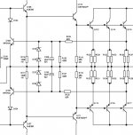
Here you got a schematic for a protection circuit as promised.
However if output impedance is no problem to you, just put in some 8 Ohms/50W resistors.... Then you are sure that your amp survives a shortend output (for a short while) 😉
Here you got a schematic for a protection circuit as promised.
Attachments
Thank you, i understood, and...
I also use Multisim 2001, but you really make an wonderfull collor combination.
OK for components, and test circuit, if simulate good, will work.
regards,
Carlos
I also use Multisim 2001, but you really make an wonderfull collor combination.
OK for components, and test circuit, if simulate good, will work.
regards,
Carlos
The output impedance is not affected as much as you think because the resistors are inside the feedback loop.
Most amps have the emitter or collector resistors inside the feedback loop.... Except for NFB amps 😉
- Home
- Amplifiers
- Solid State
- short circuit protection