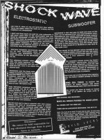
I posted this ad from the 90's in another thread and thought it might deserve a thread of it's own. Does it belong in the subwoofer forum or the exotics? Who knows... It is an ad to order the plans for a Lucus electrostatic sub. The ad makes some bold claims and I am wondering if anyone has any experience or opinions with this design.
Attachments
I searched before I posted and found nothing here. But if it has been discussed before I guess we shouldn't talk about it again. Feel free to delete thread if you see fit. Sorry.
It got a brief mention towards the end of a thread called "Electrostatic AMT?" that I started a few years ago. Any mention of David Lucas seems to generate more discussion on his business practices than the performance of his products! http://www.diyaudio.com/forums/planars-exotics/153220-electrostatic-amt-21.html
Have a read from post 203 onwards.
Keith
Have a read from post 203 onwards.
Keith
Thanks for the link. I guess the rise of the internet killed off his business model. If I would have had the money back then, I could have easily fallen for it. Oh and I emailed what might be his website to try and get details...
Last edited:
Well, I fell for the Lucas stuff...bought all the electronics he offered at the time and kits to make four 2' x 3' ESL panels per his plans. That was in 1995, and it all still works. Took me a long time to figure out that the panels should not be driven full-range, contrary to Lucas' claims. I use them now with an electronic crossover (around 330 Hz) and they sound excellent (to my taste, anyway.)I bought his subwoofer plans but never made one.
I have read that others had bad luck with Lucas taking $ and not delivering, but that wasn't my experience.
I have read that others had bad luck with Lucas taking $ and not delivering, but that wasn't my experience.
about the shockwave plans
Do you have the shockwave plans it would be nice to upload the plans to see if it true about the shockwave ads say if its possible post them up I want to give it a try I have some money to burn for now please post plans for the shockwave if you have it
Do you have the shockwave plans it would be nice to upload the plans to see if it true about the shockwave ads say if its possible post them up I want to give it a try I have some money to burn for now please post plans for the shockwave if you have it
Well i was in the Audio Biz at the time an spoke with him more than once on the phone...got all the info...but i have had Acoustat like forever....
An never moved on the ESL..I dug the look of the crved panels...
.I know you had to pay $$$ for the ESL sub Bild info...like $500.US right ...
Well i gess people today that dont Diy...pay Big $$$ for ESL...
Lucas may have been a littel lite...but it was a start..... i gess.. less you lost cash...
Thanks for the info...cant get any money back now.... so there you have it...
Anyone know if the Shockwave ever worket??... or wind any of his transfourmers???
 Please do NOT post the Shockwave plans here due to copyright considerations. You may post hand drawn copies if you wish. Posts and Titles in all caps is not encouraged. I recommend you (re)read the forum rules.
Discussions of this fellow and his business practices have been done to death here and elsewhere.. However carry on.. 😀
Discussions of this fellow and his business practices have been done to death here and elsewhere.. However carry on.. 😀
That's what PM's are for.
And the SHOCKWAVE was marketed in all caps so I thought it appropriate.
I have been thinking of taking four 9" Acoustat panels into a corner to emulate this Lucas Shockwave design...I need two more 9" Panels tho...
I wouldn't mind see how he oriented the panels into a corner tho...at least give me a place to start...planning on getting back to that project soon - currently on another project...
if you do send out any info, I would appreciate a copy - thanks!!
I wouldn't mind see how he oriented the panels into a corner tho...at least give me a place to start...planning on getting back to that project soon - currently on another project...
if you do send out any info, I would appreciate a copy - thanks!!
I just found a little more info about the Lucas stuff,
Here is a link to links in this forum for those of you whom missed it,
View Profile: diy speaker guy - Techtalk Speaker Building, Audio, Video Discussion Forum
This one is remarks posted on TAC,
Do It Yourself - Electrostatic Speakers - Material: - David Lucas
The plans to the Shockwave system are very vague.
It is basically a compounded diaphragm system.
There is no info on the D/S spacing except for using some sort of foam material for mid panel supports.
The mention of using hot glue for these supports is absurd as one would assume using it to glue them too diaphragm!
There is no mention of the specs for the transformers as this plays a very big part regarding the D/S spacing and bias voltages.
There is no mention of how the panels are wired and I would assume that they are in Parallel.
But, this is confusing because he goes into this concept of canceling the back wave with the extra panels to help focus the front wave from minimizing dipole cancellations!
But there is no mention of how they are wired.
He does show some high valued resistor in series with the panel stator's and this is fine as this forms a low pass filter with the capacitance of the panels.
He doesn't specify a particular value but states that they are somewhere between 500k and 3 Meg ?!!!
Nor does he state what power rating the resistors should be.
He states that he uses Lincane for the stator's but no mention of any types of insulative coating that should be used on them.
The same goes for what to use for the Diaphragm and its coatings.
He say's that they can be operated in Mono or Stereo.
The V shape is for mono but no mention of placement in the room.
I assumed that the V setup was to be placed in the corners of the room but upon closer reading there is no mention of this and it appears that it is placed in the middle of the L&R speaker channels for mono.
For stereo he says to separate the two stacks forming the V and set them in close proximity to each of the L&R speakers.
In the schematic it shows that the Main speakers in series with the ESL transformer.
Depending on the primary inductance of the transformer this sort of forms some kind of crossover.
I have been recently experimenting with this type of circuit configuration using a Spice program and it is not easy to get everything to match up correctly and does take a few large capacitors to do so.
He shows no capacitors not to mention the parameters of the transformer.
However, I have mentioned before I do like the concept of compounded Diaphragms for low frequency's.
ML uses this very same concept in there largest system.
I have been thinking about a system based on this concept by corner loading to 8 1'x4' panels in each corner of the room parallel to the walls.
With each panel having two or maybe three diaphragms in each panel with a very large D/S on the order of about .125".
This type of system would require a very high Bias voltage and I have already worked out a possible direct drive system to eliminate all of the iron that would normaly be required for low frequency operation.
The concept is very easy really but it takes a lot of displacement to attain good bass out of an ESL type system or even using dynamic drivers as well.
I think that having the compounded Diaphragm would be a necessary factor in order to have good control over a very light large area, high excursion diaphragm planar system.
In the construction of the panels it appears that each cell was layered with some open celled foam material and this would provide for some very high dampening of the diaphragm and its resonances.
I do plan on experimenting on such a system soon and I am open to any ideas or suggestions of this concept.
FWIW
Cheers!!
jer 🙂
Last edited:
I realize it is far after the fact (just found this by way of Google), but I would also appreciate a PM of those plans. I've been curious for many years!
Indeed very interesting. Yes a pm would be interesting.Thanks!
I realize it is far after the fact (just found this by way of Google), but I would also appreciate a PM of those plans. I've been curious for many years!
I realize it is far after the fact (just found this by way of Google), but I would also appreciate a PM of those plans. I've been curious for many years!
I realize that this is a really old thread, but I also came across it via Google while searching for info on the Shockwave after seeing an advert in some old magazines. For anyone who may still be interested I came across this site with further details David Lucas Shockwave ESL
Allen
- Home
- Loudspeakers
- Planars & Exotics
- Shock Wave Electrostatic Subwoofer!!!