I've built a Leach low TIM amp and it works fine (I've just had it going in a temporary cabinet for the last few months). Now that I'm going to stick it into a permanent case I was going to have the cabinet partitioned into a "noisy" side and a "quiet" side by a sheet of metal.
On the noisy side I will have the transformers and obviously the circuit boards etc shielded from the transformers on the quiet side. What side should I put the bridge rectifier and the power supply smoothing caps on?
On the noisy side I will have the transformers and obviously the circuit boards etc shielded from the transformers on the quiet side. What side should I put the bridge rectifier and the power supply smoothing caps on?
I might very well be wrong, but I'd think you should put the bridge with the transformer and the caps near the output stage.
I would put bridge rectifier on noisy side and smothing caps on a quiet side as close to output stage as possible.
Bridge
Split the filter caps. Make the transformer_ bridge_filter caps loop small to minimize inductance and radiated noise. Run the DC to the rest of the filter caps near the output stage. Separate bridge for negative and positive voltages also highly recommended.
Split the filter caps. Make the transformer_ bridge_filter caps loop small to minimize inductance and radiated noise. Run the DC to the rest of the filter caps near the output stage. Separate bridge for negative and positive voltages also highly recommended.
For my Aleph 2, I was planning on using separate bridges. Are there any special grounding requirements for this configuration. I assume the negative supply's + connects to the positive supply's -.
Smack in the face!
Peter,
We are begining to get pissed off because we can't build stuff with the quality you can. Most of us have to suffice wuth bubble gum and toothpicks.
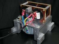
Your PSU looks good.
Jam 😀
Peter,
We are begining to get pissed off because we can't build stuff with the quality you can. Most of us have to suffice wuth bubble gum and toothpicks.
Your PSU looks good.
Jam 😀
This is not my intention to **** anybody. I just wanted to show what is possible when you DIY long enough. There is lot of people who build amps on this forum. I think there should be more pics of stuff people do so we could all exchange ideas and learn. They more usefull than cats and dogs pics on this forum.
Peter
Peter
Peter,
Only in jest. Cats and dogs are important to some people not to mention motorcycles.
By the way Jocko has a good question.
Jam
Only in jest. Cats and dogs are important to some people not to mention motorcycles.
By the way Jocko has a good question.
Jam
I thought it shields transformer, isn't it? There is another plate in front which is not installed yet.
Mu metal
Has anyone used mu-metal sheets to shield transformers and other EMI noise makers.
Dale
Has anyone used mu-metal sheets to shield transformers and other EMI noise makers.
Dale
I wouldn't be too worried about shielding transformers. Many manufacturers don't shield their transformers (Pass D1). In my projects transformer never was a problem, if I shield it it's only because enclosure couldn't be done other way and it's (enclosure) part of a shield.
Aluminum isn't very good at shielding
The cage that a standard PC Power supply is enclosed in is pretty good. I built a switcher/single chip amp in one and it doesn't bother anyone. MuMetal is damned expensive, but if you find a dead oscilloscope, chances are that you have a nice little supply. If I recall correctly, MuMetal changes its characteristics if bent, however. If you really, really need to shield you should have a brass screen on the fan! (Decades ago I worked in a completely RFI free quiet room -- multiple brass screens, brass finger stock on the doors -- we even used lead acid batteries to power the stuff inside! All this to see how some protons changed their spin when monkeyed with). Oh, and btw again, National Semi has hints on shielding on their white paper dealing with EMI/RFI.
The cage that a standard PC Power supply is enclosed in is pretty good. I built a switcher/single chip amp in one and it doesn't bother anyone. MuMetal is damned expensive, but if you find a dead oscilloscope, chances are that you have a nice little supply. If I recall correctly, MuMetal changes its characteristics if bent, however. If you really, really need to shield you should have a brass screen on the fan! (Decades ago I worked in a completely RFI free quiet room -- multiple brass screens, brass finger stock on the doors -- we even used lead acid batteries to power the stuff inside! All this to see how some protons changed their spin when monkeyed with). Oh, and btw again, National Semi has hints on shielding on their white paper dealing with EMI/RFI.
Mu Metal
Yup, MuMetal does not like to be bent..... curves are fine, sharp bends not a good idea.
Given the price of MuMetal, 10 ga sheet steel is the real "deal". Use plenty, it's cheap! Just don't magnitize it by placing it within a rapidly collapsing magnetic field.
Cyclotronguy
Yup, MuMetal does not like to be bent..... curves are fine, sharp bends not a good idea.
Given the price of MuMetal, 10 ga sheet steel is the real "deal". Use plenty, it's cheap! Just don't magnitize it by placing it within a rapidly collapsing magnetic field.
Cyclotronguy
split the caps like harry says
i put all my caps on my amp's signal PCB (15,000uF per rail), right by the output devices, and i think it was a mistake. i think there was some noise radiation from the ripple currents in and around the caps which in turn caused some audible hum. better to put a good amount of storage capacitance right after the rectifier to take care of ripple, and keep that part of the supply isolated from the signal circuits. then add on some more bypassing right by the output devices to lower impedance, provide instantaneous reserves, and compensate for any lead inductance. in any case the power going to the signal PCB should already be as close to pure DC as possible to minimize noise. i would say put around 10,000uF per rail locally, and put the rest by the rectifiers. that's assumming you have at least 20,000uF total storage per rail. the amp should still be able to work w/o the local supply decoupling, the extra caps by the output stage are just the icing on the cake IMHO.
marc
p.s. mccormack did something like this a while back. they called it "Distributed Node Amplifier" or something. i don't think it was really much more than supply caps spread out over the circuit.
- Status
- Not open for further replies.
- Home
- Amplifiers
- Solid State
- Shielding of power supply.