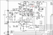
I've got a Sherwood S-2620 CP stereo receiver on my bench right now. It's not worth much, and probably not worth my effort, but I feel compelled to get it going. Figured this would be a good learning project at the very least.
It was functional when I put it storage several years ago, but now the phono stage has an issue. When pulled from storage the right channel behaved normally, the left channel has no audio signal but the left speaker pulsed in and out about twice per second with a loud clicking. Sounded like a heart beating. This only impacts the phono channel, CD/AUX, AM, and FM, all function perfectly. So the issue is within the phono eq/pre-amp portion of the board.
The dual opamp IC was faulty (TA75558P was on the board, different from schematic), pulled it out, popped in a NE5532AP as a replacement. All I had on hand. Right channel continued to function, left channel no longer pulses, but is just silent.
The left channel electrolytics have been pulled, and are confirmed to be healthy. Both Q501L and Q502L tested perfectly with a Peak analyzer when pulled from the board, so no issues there. Rail voltages appear to be normal. The ceramic caps all test OK. Replaced R505 and R506 just to rule that out. No improvement.
Kind of at a loss here, any suggestions on what to check next?
Last edited:
The electrolytics may have started drying out, its 40 years old or so - in particular I'd suspect C506L and C510L
Attachments
The electrolytics may have started drying out, its 40 years old or so - in particular I'd suspect C506L and C510L
The electrolytics were replaced a few years back before it went into storage. I pulled the ones in the left channel and verified health just to rule out any early failure. So all checks out there.
Not sure how 😀😛.......🙄
Right half of the dual opamp IC survived apparently.
I would check all switches in the receiver, first.
Switches and controls have all been verified. I wish it was that simple with this one.
Right half of the dual opamp IC survived apparently.
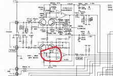
You missed the point/joke, take a look at the circled area in my attached circuit
You missed the point/joke, take a look at the circled area in my attached circuit
Ahhhh, I see now.
> left speaker pulsed in and out about twice per second
Motorboating. I would look to C512 C513; I can't know if these are in "left channel electrolytics".
I must also wonder how a 4558 would die here.
Motorboating. I would look to C512 C513; I can't know if these are in "left channel electrolytics".
I must also wonder how a 4558 would die here.
Took a few days off from this to come back to it with a clear mind. Things are a bit weird here, but still trying to find the source.
Pulled C512 and C513, both test OK.
—Prior to replacing the failed opamp, the voltages were as follows——
The base of Q502L had measurable voltage on it slowly varying from .001VDC to about .380VDC. The base of Q502R had 0VDC.
Measuring DC on the phono signal path at the input selector switch, volume at 0, the right channel showed 0VDC, the left channel gave slowly oscillating values ranging from -7.5VDC to +7.5VDC.
1. A Output = Varied from -10VDC to +14VDC
2. A -Input = Varied from +4.4VDC to +5.3VDC
3. a +input = Varied from +5.3 to +5.9VDC
4. V- = -15VDC with about .5VDC variance
5. B +Input = +5.3 to +5.4VDC
6. B -input = +5.3 to +5.4VDC
7. B Output = 0VDC
8 V+ = +15VDC with about .5VDC variance
—After replacing the failed opamp voltages are as follows —
Rail voltage - Approx +11VDC and -11VDC
The base of Q502L had measurable voltage on it, -0.25VDC The base of Q502R had 0VDC.
1. A Output = 0VDC
2. A -Input = 2.8VDC
3. a +input = 5.15VDC
4. V- = -8.2VDC with some variance
5. B +Input = 3.02vdc
6. B -input = 3.02vdc
7. B Output = 0vdc
8 V+ = 8.43vdc
How can you state the rail voltage is 11V and then say it's -8.2v and +8.4v ??
The IC is either damaged or the PSU is, it's being pulled down to ~8v on both rails.
The rails should be closer to 15v (+&-) as indicated by the schematic.
Remove the IC and check rails again
You replaced like for like ? , and it's in the right way round ?
Original IC was a TA75558P, schematic spec'd a NJM4558DD. I swapped in a NE5532AP dual opamp I had on hand to test with, figured this wasn't an issue since the right channel continued to function with this IC.
The rail voltage was measured on the posts where the power supply reaches the board, so the voltages at V+ and V- on the IC are dropped with the IC installed.
With the IC pulled pins 4 and 8 in the socket measure roughly -16VDC and +16VDC. As do the posts where the power supply connects. So the voltages are rising to normal levels with the IC pulled.
I found a 4558D JRC in my parts bin, popped that in. Still no left channel audio, but pins 4 and 8 are at 15.5 VDC. I guess I'll use that for troubleshooting going forward.
Last edited:
I'd flip both transistor pairs to the other channel (now that you've replaced the obviously faulty or incorrect opamp) and retest
Alright, I found the problem. Got too tied up looking at this darn IC I totally missed something obvious.
I decided to trace the signal with my oscilloscope too see what's going on in comparison to the right channel. Realized no signal was found at the base of Q501L. Touched a signal generator to it, boom, left channel audio....
Before I put this in storage I had replaced the filter caps, it had some minor hum issues that were cured by that. I replaced some other electrolytics that didn't test perfectly, C502R and C502L were two of those. I pulled and tested C502L early in troubleshooting, no issues. The problem is, on the PCB the positive end of C502L doesn't go anywhere..... It's just on it's own isolated pad with no trace coming off of it. There must have been a jumper under the board originally or something, really bad design. Missed it when I swapped the cap. Added in a jumper, and it's back to normal.
The original dual op amp is toast, no sound with it installed. The circuit seems to function fine with that 4558D JRC I had handy, this is a close enough replacement for the original spec NJM4558DD right? Is there a big difference between the D and DD? The NE5532P and NE5532AP I have seem to function just fine as well. Open to any thoughts on how to proceed with an appropriate path here.
I appreciate all the help from everyone, I should have caught this earlier, but I learned a lot in the process.
Last edited:
Neither NJR nor TI have any data on the DD version, the datasheets for both brands only speak the D version.
This is despite places like mouser (apparently) stocking both a D and DD and an DX variant (all supposedly DIP packages)
They actually have stock on the D and DD version too.
Out of curiosity I might just fling them an email to ask if they can tell me a difference.
Search results for: njm4558d Operational Amplifiers - Op Amps – Mouser United Kingdom
They all refer to the same datasheet, which makes no mention of a DD version or a DX
Yeah, I was just looking at the same datasheet, no help there. I noticed Mouser lists the DD as "high gain" and the D as "general purpose". The DD has higher Operating Supply Voltage on the Mouser description as well.
They're cheap enough, ordered a handful to play with, I'll test them out and see if there is any difference in practice.
Thanks again for the help here.
They're cheap enough, ordered a handful to play with, I'll test them out and see if there is any difference in practice.
Thanks again for the help here.
Out of sheer curiosity I've set in motion a tech support request to ask the question.
Will be interesting because they have stock of both
Will report back when I get an answer
Will be interesting because they have stock of both
Will report back when I get an answer
I got a reply after mouser contacted the manufacturer:
NJM4558D has the catalog standard characteristics.
NJM4558DD and DX, they have the same characteristics but just a different name for our internal process.
But after saying they're the same thing then they show me two tables outlining a slightly different single spec difference for the two variants 😕
4558D - Equiv Input Noise Voltage: (RIAA, Rs=2k2 30KHz LPF) VNI 1.4uVrms typical (with no min or max specified)
4558D-X & D-D Equiv Input Noise Voltage: (RIAA, Rs=2k2 30KHz LPF) VNI 1.8uVrms max (with no min or typ specified)
Not really a full answer as they don't give the max on the D version, so I'd just treat them as equiv parts.
Thanks! My Mouser order came in with both NJM4558D and NJM4558DD. Tried both, noticed no discernible difference. Installed a NJM4558DD and put the unit back together.
- Home
- Amplifiers
- Solid State
- Sherwood S-2620 CP phono stage repair