Maybe Sherman accidently misled you. He may have confused CT and dual secondaries or may have unwound the CT a little to separated the coils. 😉
hiya greg.
indeed i do think he has accidently misled us and himself. i've read through his posts most carefully trying to figure out what, and the funny thing is i'm not finding it.
i'm certain he had a CT and did not do an operation. he describes the CT most clearly. also when Steve (i think) gave up in that sub-thread, it was because he went by the operation route himself.
so i dunno man. it's an odd one and got me intrigued.
... i'm also still looking for that [expression deleted] thread about the dual grounds that you suggested i find. no luck, but i keep turing up little gems like this one.
Greg Erskine said:Maybe Sherman accidently misled you. He may have confused CT and dual secondaries or may have unwound the CT a little to separated the coils. 😉
Nope, my CT transformer had no wires coming from it, either on the primary or secondary side. The connections were via quick connect. There was only one tab for the CT.
I crimped a single wire into the quick connect that connected to the trafo. I ran that wire to a euro style terminal strip. I came out of the terminal strip with two wires which I connected two wires which I connected to AC1N and AC2H.
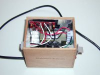
eva, the white wires meet at the channel PCBs.
sherman, thank you for joining in. as you can tell, i'm confused and bemused by this.
are your diodes all oriented the same way? (heatsink side up.) i can't quite make that out.
also i see four wires on the tx side of the right terminal. but the second green i see is just the loop you made so the CT would have two outputs, yes? this would be as you have described and drawn before.
(pretty box btw. very tidy. it doesn't get warm in there?)
Yes, this is really baffling! I have those exact same PCB's and exact same transformer, but I cannot come up with any theories! I know that the transformer has dual primaries, and no mention has been made of the primary side yet. But even with the possibles cases of the xfrmr incorrectly wired for 240V service or with the primaries out of phase I cannot think of anything!
ofb said:eva, the white wires meet at the channel PCBs.
sherman, thank you for joining in. as you can tell, i'm confused and bemused by this.
are your diodes all oriented the same way? (heatsink side up.) i can't quite make that out.
also i see four wires on the tx side of the right terminal. but the second green i see is just the loop you made so the CT would have two outputs, yes? this would be as you have described and drawn before.
(pretty box btw. very tidy. it doesn't get warm in there?)
I tried a couple ways of hooking things up using the CT trafo and this one worked just fine. I have no idea why as other seem to think it shouldn't.
All the diodes are installed the same way.
Exactly right about the green wire. It goes from the CT on the trafo to one position on the terminal strip. I looped it to the other position so I could run two leads to the board.
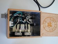
I took the output from the board- (V+, PG+, V-, PG-) to that 6 position Molex connector. I also connected my earth/safety ground (green wire in the three conductor AC cord) to it and one position is unused. Five wires make up the umbilical that runs from the PS box to the amp box. The chassis ground of the amp box connects to the same point that the safety ground goes to.
The cases for both the PS and for the amp are cigar boxes. I lined the insides of the boxes and the sliding lids with aluminum tape for RF shielding (not sure how necessary it was). The amp case has external heat sinks for the chips so they stay pretty cool. I figured if the PS case got warm I could slide the top open a bit for ventilation. That seemed to work fine.
Actually I sold the amp sometime last year but I still have a few cigar boxes and a few chips laying around so maybe I'll build another one! (Don't have anymore of those trafos though.)
in the words of ralph wiggums, "but that's unpossible!"
how very, very strange.
please let me ask a question that i know you have answered before in the other thread.
the PG- and the PG+. did you run both of these to both channel PCBs, or did you only run one to each channel PCB?
how very, very strange.
please let me ask a question that i know you have answered before in the other thread.
the PG- and the PG+. did you run both of these to both channel PCBs, or did you only run one to each channel PCB?
leadbelly said:Yes, this is really baffling! I have those exact same PCB's and exact same transformer, but I cannot come up with any theories! I know that the transformer has dual primaries, and no mention has been made of the primary side yet. But even with the possibles cases of the xfrmr incorrectly wired for 240V service or with the primaries out of phase I cannot think of anything!
Well I got the correct AC voltage out of the secondary so I'm pretty sure it is wired correctly. 😀
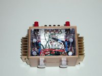
I don't know why this works or if it would work with a different CT trafo, all I know is that is does indeed work and the output from the board was +33VDC and -33VDC.
I actually also hooked this up using two bridges as well and that setup worked too. Here is a shot of that before the wiring was completed. (I had to add my own caps of course and in the end the board that Brian supplied was smaller and easier to mount so I went with it.)
Attachments
ofb said:in the words of ralph wiggums, "but that's unpossible!"
how very, very strange.
please let me ask a question that i know you have answered before in the other thread.
the PG- and the PG+. did you run both of these to both channel PCBs, or did you only run one to each channel PCB?
Good question, no one else has asked it. Attached is a pic of the finished amp case interior. It is sort of hard to see but I connected the wires from the Molex connector to another terminal strip inside that case. I then connected two wires into the other side of each position of the terminal strip. I then ran one of those wires to each amp.
Long explanation short, yes, both PG+ and PG- run to both amp boards.
Attachments
Sherman you get a gold star: your mystery is intact!
i have no ideas left.
the only thing i think is even possible now is that when you doubled the wires at the last terminal block you ran the new pairs to the same boards. meaning PG+1 and PG+2 went to one channel and the PG-'s to the other. but that's still a rather dubious circuit.
i have no ideas left.
the only thing i think is even possible now is that when you doubled the wires at the last terminal block you ran the new pairs to the same boards. meaning PG+1 and PG+2 went to one channel and the PG-'s to the other. but that's still a rather dubious circuit.
Each board did get connected to all four lines from the rectifier board. I also tested the voltages at each point so I'm confident they are correct, moreover the amp worked, and worked well!
I was actually hoping that other people would be able to do this! It would be nice to be able to use all those CT trafos out there where it isn't easy or even possible to get into the taps and untwist the center tap to make dual secondaries.
I haven't tried this again with other trafos. I bought four of those (closeouts or surplus from Parts Express) and did this with those four but since then I've had dual secondaries so I haven't thought much about it since then.
Maybe someone above my salary grade will figure this one out!
the Force is strong in this one
indeed this is the most important thing. it's all about the music.
please, do make sure you have a fuse on the primary side of the tx when you try this again. this is standard practice of course, and you likely already do it, but i just want to emphasize it because that fuse will save all when your magic technique fails.
i'm looking forward to it! you have done the impossible, really. 😉 please continue to use your powers for Good.
Originally posted by Sherman
...moreover the amp worked, and worked well!
indeed this is the most important thing. it's all about the music.
I haven't tried this again with other trafos. I bought four of those (closeouts or surplus from Parts Express) and did this with those four but since then I've had dual secondaries so I haven't thought much about it since then.
please, do make sure you have a fuse on the primary side of the tx when you try this again. this is standard practice of course, and you likely already do it, but i just want to emphasize it because that fuse will save all when your magic technique fails.
Maybe someone above my salary grade will figure this one out!
i'm looking forward to it! you have done the impossible, really. 😉 please continue to use your powers for Good.
Re: the Force is strong in this one
Years ago I let the magic smoke out of a transformer because I was in a hurry and thought the circuit breaker on a power strip would protect things. WRONG! I paid too much for the tx to smoke it before even using it! Since then I've either taken the time to wire the fuse into the circuit or I use a PS "mule" I built.
The mule is an MDF board with rubber feet and a metal panel on one end. The panel has an on/off switch, 3 conductor AC cord and a fuse holder. The power feeds a terminal strip mounted on the MDF. When I need to test a new tx or temporarily set up a PS connecting a few wires to the terminal strip lets me do it quickly and with fuse protection. (Being impatient I know I'd smoke other components if I hadn't taken 20 minutes to put this thing together.)
I should look on the parts shelf for another CT trafo and see if I can make this work with a model other than the one I used previously.
Anyway, I'm out of ideas and have to chalk it up to having assembled the first one on the third Tuesday after a full moon or something. 😕
ofb said:
...please, do make sure you have a fuse on the primary side of the tx when you try this again...
i'm looking forward to it! you have done the impossible, really. 😉 please continue to use your powers for Good.
Years ago I let the magic smoke out of a transformer because I was in a hurry and thought the circuit breaker on a power strip would protect things. WRONG! I paid too much for the tx to smoke it before even using it! Since then I've either taken the time to wire the fuse into the circuit or I use a PS "mule" I built.
The mule is an MDF board with rubber feet and a metal panel on one end. The panel has an on/off switch, 3 conductor AC cord and a fuse holder. The power feeds a terminal strip mounted on the MDF. When I need to test a new tx or temporarily set up a PS connecting a few wires to the terminal strip lets me do it quickly and with fuse protection. (Being impatient I know I'd smoke other components if I hadn't taken 20 minutes to put this thing together.)
I should look on the parts shelf for another CT trafo and see if I can make this work with a model other than the one I used previously.
Anyway, I'm out of ideas and have to chalk it up to having assembled the first one on the third Tuesday after a full moon or something. 😕
- Status
- Not open for further replies.
- Home
- Amplifiers
- Chip Amps
- Sherman & the Center Tap Mystery