Let's start with the basics.
In order to produce similar power from a substantially lower voltage (eg 500/680=73%), you will need substantially more current (100/73=137%). None of those "dropping" methods will allow you to do that, if the PT is even capable of it.
Assuming you can live with less power than the original amp, I would try either a bucking trafo or a series string of power zeners. I think you will find that reducing the cap size will work better than dropping resistors but still give poor load regulation.
Subtraction methods, like zeners or synthetic equivalents have the big disadvantage of magnifying ripple and other voltage variations.
If power dissipation is acceptable, a series regulator is preferable: it will not only drop the voltage, but also reduce the ripple, the output impedance and improve the line regulation.
For this kind of voltage, let's be honest: any slip, even a minor one will result in magic smoke escaping and molten silicon.
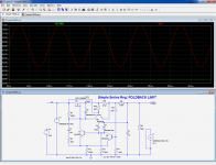
The type of regulator shown below is simple, inexpensive, and can be made to be reliable thanks to the foldback limiting.
It can also provide a slow start function if desired, see one the high voltage threads I started.
These circuits have been tested at voltages around 300V. With suitable components (mainly the pass element), they should work at any voltage, but from experience, even with suitable components, difficulty increases as the square of the voltage: a small inconsequential "shortcut" at 300V may prove fatal at 600V (in theory, only the differential I/O should count, but in practice, the absolute voltage does very much matter: at one time or another, your pass element will see the full absolute voltage. Good luck anyway).
You have been warned, here is the adapted (and simulated only) circuit:
If power dissipation is acceptable, a series regulator is preferable: it will not only drop the voltage, but also reduce the ripple, the output impedance and improve the line regulation.
For this kind of voltage, let's be honest: any slip, even a minor one will result in magic smoke escaping and molten silicon.
The type of regulator shown below is simple, inexpensive, and can be made to be reliable thanks to the foldback limiting.
It can also provide a slow start function if desired, see one the high voltage threads I started.
These circuits have been tested at voltages around 300V. With suitable components (mainly the pass element), they should work at any voltage, but from experience, even with suitable components, difficulty increases as the square of the voltage: a small inconsequential "shortcut" at 300V may prove fatal at 600V (in theory, only the differential I/O should count, but in practice, the absolute voltage does very much matter: at one time or another, your pass element will see the full absolute voltage. Good luck anyway).
You have been warned, here is the adapted (and simulated only) circuit:
Attachments
Hi,
Thanks for all the input! The series regulators look fine, but I agree with the sentiment that at 600V, it may turn into a little stick of silicon dynamite🙂
I like the idea of using smaller value caps to drop it and follow it with a nice beefy LC filter which should take care of the ripple and poor regulation issue.
"Why not get a PT that puts out the right voltage?" As much as I plan things, I didn't think this out very well. These will be repurposed Bogen amps. The biggest issue at this point is that I have a 3mm top plate cut for a through hole transformer, and I'm not too interested if figuring out how to patch it to look nice.
Thanks for everyone's input! I used PSDII last night to play around with a small cap value into an LC, and it looks pretty promising.
The type of regulator shown below is simple, inexpensive, and can be made to be reliable thanks to the foldback limiting.
Mmmm... no. Reliable, maybe, depending on one's expertise. Inexpensive and simple, no. Building a regulator from scratch is more expensive than buying the right trafo, not to mention the time/effort. We're talking about a regulator that needs to dissipate in excess of 50W at high voltage.
I like the idea of using smaller value caps to drop it and follow it with a nice beefy LC filter which should take care of the ripple and poor regulation issue.
Do a simulation. I think you will find the load regulation of that type of PS is less than stellar. See what happens with Vout when you go from idle to max current. But understand that the simulation is largely dependent on entering the right transformer data.
As much as I plan things, I didn't think this out very well. .
This is what I was trying to tell you in your other thread a while ago. It's best to prototype it on the bench first and work out all issues before spending a lot of time and money cutting wood and metal.
I will give it a try with the small caps.
Regarding time, $$$, and mishaps🙂 No guts no glory. It's a hobby right?
Anyway, if I had gone with my original intuition, I would have been fine. My idea was to take the Bogen and beef up the supply, etc.
I was told by a number of people that the Output iron is 2.1k primary, but regardless of what frequency I test them at, I get between 4.5-5.5k.
That made the KT88 the most appealing, but I'd like to get my voltage down a little. All that being said, I have seen modern day KT88s (jj and EH) run in pentode at 700V B+ last several years in a bass amp being run very hard every weekend for hours.
So, I certainly see what you are saying about prototyping, but it is cut and I'd like to see if I can make it work with KT88s.
Another option is the 6146B. I have just never heard it in a hifi amp.
It's all for fun right?
Schematic of Bogen MO200A for diagnosis. Bogen pentode amps tend to have really high B+ regardless tube type but at least they're not Ultra-Linear designs so the screen-grid is not slammed with such high voltage. In the case of the MO200A, the screen is sitting comfortably at 335VDC. Even 8417's plate is at such high voltage, 685VDC, the tube is still pretty easy to drive as the negative bias voltage is only -19VDC.
Good luck on shaving off the high voltage!

Good luck on shaving off the high voltage!
Is there any reasonable way to shave 100V off a HV supply?
I have an amp with a doubler circuit that has a B+ of around 680VDC, and I'd like to see it come down a bit to about 580-600V
It's an old Bogen, and the PS is rated to put out some pretty high current as well, so I am inquiring as to a method to shave the voltage while maintaining the high current output.
Thanks!
Blair
you'll be surprised how the B+ drops as soon as the plates draw current and as you bias the output tubes.....
is the 680 volts unloaded or is it your B+ when tubes are conducting current?
another easy way to drop your B+ is by connecting a series resistor with your traffo secondary going to the voltage doubler..., just one 20 watter resistor can do the trick, start with a 47 ohm resistor...and work your way from there...
Thanks guys!
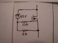
Miles, that looks pretty nice! Can the MOSFET mount to the chassis as a heatsink?
Tony, the 680V B+ is loaded from the old schematic which someone posted above. So, it is probably a 250V secondary. Unloaded, I get ~260v out of it from my wall.
"Bucking" with the spare 6.3V gets me ~240V output from my wall, so that alone probably pulled ~50V off. Adding a CL-70 will get me another small drop.
Like I said, I'm interested in dropping some B+, but not destroying the current producing ability of the transformer.
The good side to it is that I am planning to use 1/2 the output tubes, so the power transformer should have quite a bit of spare current to work with.
Something I thought of the other day is that "bucking" works to lower the B+ when used on the primary side, so why can't you "buck" the secondary with an external, additional transformer? Say, I took a 40V, 2A transformer and just used the secondary winding to drop the secondary voltage before the doubler.
Would that not work?
Like an autoformer.
Would that not work?
Like an autoformer.
that will work, but in my case a series resistor on that secondary is the cheapest way to do it...
Why not purchase a transformer which will deliver the voltage that you require?
Good idea. Then design for full wave rectification instead of a voltage doubler.
Otherwise Eli's original suggestion is probably most practical.
Hi,
Yes, Eli, and using another secondary to lower B+ seems most effective. I'm not too exited about dropping it via power resistors.
I just got a pair of 3Hy, 500mA chokes I am going to try to use via Eli's suggestion. It simulates nice and clean.
If not, I may have to suck it up and try to find another PT.
Thanks!
Blair
Series secondary resistance is good for alleviating diode induced transient issues, so I reckon that is one part of a solution package - but definetely overrate the resistor wattage as it is handling more than typical I2R calculations.
If you go the CLC route, then you may need to use poly caps for the first C (doubler stage) due to the high ripple currents, and their low capacitance will reduce the average voltage before the L and can allow you to better tune the output voltage. I've found old UPS and switchmodes to be a good supply of 400V to 680VDC rated 2-10uF caps. A loading resistor after the choke is likely needed to constrain initial turn-on B+ before the output stage bias comes up.
If you go the CLC route, then you may need to use poly caps for the first C (doubler stage) due to the high ripple currents, and their low capacitance will reduce the average voltage before the L and can allow you to better tune the output voltage. I've found old UPS and switchmodes to be a good supply of 400V to 680VDC rated 2-10uF caps. A loading resistor after the choke is likely needed to constrain initial turn-on B+ before the output stage bias comes up.
Yes,
I think that will work well.
Do you know what SS devices would be good for this application? I have a good source for TO-3 heatsink a and a decent selection of transistors.
I think that will work well.
Do you know what SS devices would be good for this application? I have a good source for TO-3 heatsink a and a decent selection of transistors.
Yes,
I think that will work well.
Do you know what SS devices would be good for this application? I have a good source for TO-3 heatsink a and a decent selection of transistors.
I don't know anything about mosfets ....never used them. I'm wondering if something like this IRFBE20 would work.
http://www.vishay.com/docs/91117/91117.pdf Looks like the IRFBE20PBF is available from Mouser if it will work.
I also have a project with a transformer that is too large. I'm sitting at 619VDC unloaded.
Last edited:
- Status
- Not open for further replies.
- Home
- Amplifiers
- Tubes / Valves
- Shaving voltage off HV supply?