hi, limited knowledge here but I'd like to try using some spare NE5532's to provide sub Low Pass Filtering before feeding a mono BTL 3116 YJ Blue Board for a sub speaker.
Not sure about the filter circuit yet but I will require dual rail and 0V for the NE5532.
I've found a Mean Well SMPS 24V / 4.2A that is small enough to fit my chassis:
https://www.meanwell-web.com/en/pro...en-frame/111-150-w/epp-150/product/EPP-150-24
My question is: Can I simply supply the 3116 amp with the 0V , 24V and then also tap a dual rail supply from it to feed the filter section?
I'm only on the PSU design part of my project so far, need to learn about OP Amps next for the filter, any suggestions would be welcome - even sign posting to some good cheap small 3116 boards that are already in mono mode.
Suggestions and solutions as to the inherent noise that an SMPS might introduce into the filter op amp section are obviously also welcome,
Stu
You can operate op-amps with 0V and +24V but will have to use caps on the input and the output. You will also have to bias the +input of the op-amps at 12V.
Filter the +24 very, very well.
Or use a DC-DC converter to give you +/- 12V (or 15). Filter that as well.
🙂
Filter the +24 very, very well.
Or use a DC-DC converter to give you +/- 12V (or 15). Filter that as well.
🙂
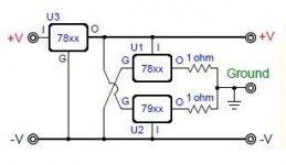
Thanks for the reply, would I be able to implement the circuit in the attached image. I would use U3 regulator at 24V and U1/U2 at +12V and -12V?
If so, could someone explain to me where I would insert some RCRC filtering?
Or would you guys recommend a DC DC converter? If so, which one?
Stu
If so, could someone explain to me where I would insert some RCRC filtering?
Or would you guys recommend a DC DC converter? If so, which one?
Stu
Attachments
Last edited:
One potential issue that I see is that the supply you linked to in post 1 has (for EMI/EMC reasons) a capacitor between the -V and supply safety ground.
I am not sure how that would affect operation.
the other is that you will have one ground for your pre-amp and a different one for the power amp.
Any signal between the two grounds will show up as signal into the power amplifier.
I would not recommend this situation.
I have used DC-DC converters such as NMA2415SC. +/- 15V @ 33mA.
Note that these (among others) require a minimum of 10% load to meet output voltage specs.
An NMH2415SC will give you +/-15V @ 67mA.
In both cases you can use an LED to "waste" a few mA to meet minimum loading.
There will be people who do not like DC-DC converters as they produce noise.
I cannot say they don't produce noise but I do say that I cannot hear noise at 80KHz or 100KHz.
🙂
Thanks Dug, I am trying to get an understanding of the grounding issues. I presume i send my IEC Mains inlet to chassis ground. The SMPS only takes the Live & Neutral.
The DC - DC Converter also does not take a ground connection but gives out a + rail and a - rail and a OV (Common)
Does the 0V Common pin from the DC DC converter go to chassis ground (Star)? Does this in turn, hold the common 0V rail to chassis ground and make the + and - rail reference from this?
Would I then build my Opamp filter......
http://xtronic.org/wp-content/uploads/2012/07/Ne5532_filtro_grave_diagram.png
...with a ground rail OV also connected to the chassis star ground?
Is this why the DC DC Converted is called an Isolated component?
I looked at other Mean Well SMPS and they all seem to have a capacitor to ground from the negative output, some even have the capacitor from ground from both the positive and negative outputs.
I haven't even looked into the minimum load that you mentioned, I did find this component ....
https://www.meanwell-web.com/en/product-info/dc-dc-converter/pcb/0-3-w/dcw03/product/DCW03B-12
....but I guess this would suffer from the same minimum load requirements?
sorry to ask so many newcomer questions,
Stu
...
Does the 0V Common pin from the DC DC converter go to chassis ground (Star)? Does this in turn, hold the common 0V rail to chassis ground and make the + and - rail reference from this?
...
...with a ground rail OV also connected to the chassis star ground?
Is this why the DC DC Converted is called an Isolated component?
...
Yes
Yes
Yes
The data sheet does not directly state this but there are two clues that this is the case....
....but I guess this would suffer from the same minimum load requirements?
...
One is the output current from XmA to 10XmA (can't remember the numbers exactly)
And the Note 4: "4.Load regulation is measured from 10% to 100% rated load."
Great, I have found the similar regulator from Murata NMH2415SC. This gives +/-12V instead of +/-15V as my filter circuit listed above requires +/-12V (although I'm sure you'd say it makes no difference to the values of the other components in the filter ciruit)
These Murata converters state that the output is unregulated - I have found this simple circuit that utilises a converter that is regulated:
Would I need to add regulation after the converter?
regards
Stuart
These Murata converters state that the output is unregulated - I have found this simple circuit that utilises a converter that is regulated:
An externally hosted image should be here but it was not working when we last tested it.
Would I need to add regulation after the converter?
regards
Stuart
And would I simply connect an LED and resistor in parallel with Cout1
and do the same in parallel with Cout2 to provide the 'waste' of a few milliamps to meet the required minimum load?
And, do i need the 1W package or the 2W package (DC DC Converter from Murata) to supply the NE5532 filter circuit.
Sorry for asking this last question but I don't know where to start in calculating the current that would flow through the filter circuit
Stu
OK, thanks for the guidance. I feel I'm getting somewhere but could really do with some advice. I have comprised a circuit to allow me to tap a dual rail supply form an SMPS that will also be powering the 3116. The dual rail will supply a simple NE5532 LPF.
I understand the reasoning behind the LEDs providing some drain so the DC DC converter sees some load but I have simply guessed where they would go in the circuit. I have also added further regulation with the use of the 7812 and 7912 but I have no idea if this will work or even if it is necessary?
My proposed circuit is attached below.
As always, any help much appreciated,
Stu
Attachments
Thanks Dug, you don't think I've over complicated it? Do I need the 7812 regulation or could I just use a simple LC filter after the DC DC Converter?
Also, do I need to ground the 3116 board?
Stu
Also, do I need to ground the 3116 board?
Stu
C2 and C9 should not be that large.
47uF is adequate.
Some DC-DC converters will shut down ( or just not start up ) with large capacitive loads.
Grounding
This is a function of safety.
I think it is a good idea to connect the GND of the output of the power supply to safety GND. (wall outlet GND)
One place... Research "star ground" theory.
The DC-DC GND (or common) goes to the pre-amp or op-amp board.
The output and GND from the pre-amp or op-amp board connects to the 3116 board along with the audio signals.
Do not attach a second GND line from the DC-DC converter to 3116 GND or star safety GND.
This is multiple ground paths and can create what is called a ground loop. Research that.
Hope that helps.
Last edited:
Thanks for all your help Dug, gave me the confidence to go ahead with my project.
Have grounded the IEC (wall) to chassis and sent the ground from the smps to that chassis point too.
The rest of the circuit will be isolated. This means my RCA inputs and outputs will be insulated from the chassis.
The 3116 board will get Ground from the SMPS by way of the the 0V, as the OV from the smps is where I took ground to chassis.
The Murata DC DC converter will also get ground by way of 0V. But this will not be passed onto the common rail of my dual rail regulated supply for the opamps?
the common rail will eventually get back to the 3116 by way of the output from the opamp filter section (signal out to signal in on the 3116) but even if the 3116 0V is connected to audio ground input on 3116 then this will still leave a star formation for grounding in my amp.
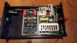
Have attached some pics just to show how pleased I am of my smps selection that fits perfectly into an old chassis I had lying around
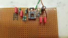
Have also attached pic of my first ever opamp build for the filter. Since choosing and building the opamp 2nd order RC filter - I have done lots more research and realised that I may be very soon building a better filter section. But if I get the PSU and grounding right then this will be quite easy to swap out. I just wanted to build my first filter around a circuit I 'vaguely' understand.
cheers for the help
Stu
Have grounded the IEC (wall) to chassis and sent the ground from the smps to that chassis point too.
The rest of the circuit will be isolated. This means my RCA inputs and outputs will be insulated from the chassis.
The 3116 board will get Ground from the SMPS by way of the the 0V, as the OV from the smps is where I took ground to chassis.
The Murata DC DC converter will also get ground by way of 0V. But this will not be passed onto the common rail of my dual rail regulated supply for the opamps?
the common rail will eventually get back to the 3116 by way of the output from the opamp filter section (signal out to signal in on the 3116) but even if the 3116 0V is connected to audio ground input on 3116 then this will still leave a star formation for grounding in my amp.
Have attached some pics just to show how pleased I am of my smps selection that fits perfectly into an old chassis I had lying around
Have also attached pic of my first ever opamp build for the filter. Since choosing and building the opamp 2nd order RC filter - I have done lots more research and realised that I may be very soon building a better filter section. But if I get the PSU and grounding right then this will be quite easy to swap out. I just wanted to build my first filter around a circuit I 'vaguely' understand.
cheers for the help
Stu
Attachments
Looks like you have a bit of space left.
Make sure you keep all of the AC section of your power supply well away from the DC/Audio parts.
Keep the amplifier inputs away from the AC line as well...noise pickup.
Make sure you keep all of the AC section of your power supply well away from the DC/Audio parts.
Keep the amplifier inputs away from the AC line as well...noise pickup.
cheers Dug, AC live will be near either the input or output of the 3116, I thought it best to put the 3116 output nearest if anything as this will be less sensitive.
Another question, have built my regulated dual rail supply but the 7812 is giving me 11.66 volts, the 7912 is giving -12.03V
Could this be a faulty 7812? I pulled it from a cheap chinese DAC. I read somewhere that the tolerance should be 2.5% max for a 7812.
stu
Another question, have built my regulated dual rail supply but the 7812 is giving me 11.66 volts, the 7912 is giving -12.03V
Could this be a faulty 7812? I pulled it from a cheap chinese DAC. I read somewhere that the tolerance should be 2.5% max for a 7812.
stu
11.66 won't hurt the cct, only limit the output swing to .34V less than with 12V.
I don't think you will need 10Vpeak signal for a 3116 amp.
I would replace it but it will work.
I don't think you will need 10Vpeak signal for a 3116 amp.
I would replace it but it will work.
According to TI's datasheet for LM78xx the tolerance is ±2% for LM78xxCT and ±4% for LM78xxACT. yours 7812 is 3% off. Not a big deal.Another question, have built my regulated dual rail supply but the 7812 is giving me 11.66 volts, the 7912 is giving -12.03V
Could this be a faulty 7812? I pulled it from a cheap chinese DAC. I read somewhere that the tolerance should be 2.5% max for a 7812.
stu
If you want to rise its output voltage then add a low power Schottky diode from ground pin of 7812 to ground, that will give you 0.2-0.4v boost.
- Status
- Not open for further replies.
- Home
- Amplifiers
- Class D
- Sharring SMPS between 3116 and Dual rail opamp filter