Got a Sharp DVD player model DV-740 that had gone bad. Switched on the wall plug, no standby light, unable to power up the unit. Suspect some components on the power supply board are dead. Any service manual, schematics & advice?
Thanks!
Thanks!
My guess it's a smps, they tend to be quite complicated devices.
Repairing it might only be possible using a scope...🙁
Repairing it might only be possible using a scope...🙁
v-bro said:My guess it's a smps, they tend to be quite complicated devices.
Repairing it might only be possible using a scope...🙁
Not really.DVD players' SMPSs are simple stuff.Bad symptoms are blown fuse,shorted semiconductors,opened circuit resistors,caps problems................
But Assyst,you need to open up the casing to check it.
I have checked & replaced some of the components but still it doesn't power up (no standby light on). I went to some of the local electronics shops but they can't identify some of the components rating. Perhaps a service manual & schematics might help.
Attachments
Don't have the schematic nor service manual, but from the picture it appears that there isn't any switcher IC?? Either that or it's under the board... you'll be very lucky if it's a 'discrete' switcher - good probability of getting it fixed.
Cheers
Cheers
Hi, Thanks for the reply. The switcher IC should be the one near the big capacitor. I have changed that. I think the big capacitor maybe the problem. Now i recalled seeing some electrolyte coming out of the base.
The big capacitor would be your mains filter. Mains power comes in, goes through some line chokes (Toko) and line capacitors (the blue ones), then into a rectifier (the four diodes near the two Toko). That should be a 350 or 400V electrolytic, maybe 220uF... Is there rectified DC on it? It should be about equal to (your line voltage * 1.414).
Cheers
Cheers
You are lucky,dude😀 .It a Fairchild Power Switch(FPS) based SMPS that's definitely a stable stuff and easy to repair incase of failure.I suspect that the start-up resistor might be open circuit.But if so,PLEASE BE CAREFUL as the the electrolytic caps might store a few hundred volts of DC and make you jump around .
.
Your part number should be the popular KA5x380R.I attached the link for your reference.
www.fairchildsemi.com/an/AN/AN-4141.pdf
BTW,is your DVD player based on a DVDROM and an ESS chipset???
.Your part number should be the popular KA5x380R.I attached the link for your reference.
www.fairchildsemi.com/an/AN/AN-4141.pdf
BTW,is your DVD player based on a DVDROM and an ESS chipset???
i have one of these dvd players also faulty.. but its different, mine the standby light comes on and all the voltages from power supply look ok.. i just cant get the thing to come out of standby :S
Owen
Owen
Do you have any voltage on the 5v-0v-12v connector ? (red/black/black/yellow)
Have you checked the secondary caps for signs of leakage or bulging ?
I would start by changing all the electrolytics on the secondary.
Andy
Have you checked the secondary caps for signs of leakage or bulging ?
I would start by changing all the electrolytics on the secondary.
Andy
Leolabs said:I suspect that the start-up resistor might be open circuit.But if
...
www.fairchildsemi.com/an/AN/AN-4141.pdf
Good one Leolabs!
poynton,
I don't think the power supply will produce 5V/12V on the connector you are referring to, unless commanded to by the control circuit of the DVD player - no standby light probably means no power for the DVD controller...
Cheers
Hi, thanks for all the input, the big capacitor is OK, no electrolyte leaking from the base. I think the manufacturer had put some kind of glue to support it. I have mistaken that for leakage. The rest of the capacitors look fine to me, no bulging.
There are no voltages output from both connectors (the color one & the white one). This kind of make me think that there are some components on this board gone bad.
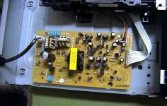
Are these diodes (circled in red)? Their legs are black, maybe they are burnt. I did ask some of the electronics shops but they can’t tell the rating. There are “10 1H” printed on it. Any idea?
There are no voltages output from both connectors (the color one & the white one). This kind of make me think that there are some components on this board gone bad.
Are these diodes (circled in red)? Their legs are black, maybe they are burnt. I did ask some of the electronics shops but they can’t tell the rating. There are “10 1H” printed on it. Any idea?
Attachments
Those that you have encircled are diodes - highly doubtful that there is anything wrong with them (on the basis that each one will produce ONE output voltage, but in your case ALL output voltages are not there).
It is highly probable that the PS isn't self-starting, just as Leolabs has said. Check the startup resistor (get the pdf and read through it).
Cheers
It is highly probable that the PS isn't self-starting, just as Leolabs has said. Check the startup resistor (get the pdf and read through it).
Cheers
They maybe out or may not.You need a DMM with a 'Diode Test' to prove them.Those are usually schottky diode,can be subsitute with this part number,SR360.
Anyway,did you check on my link provided for you???You need to make sure the primary side is OK first then you can proceed to the secondary side.
Still,take my words:check for open circuit start-up resistor first.🙂
Anyway,did you check on my link provided for you???You need to make sure the primary side is OK first then you can proceed to the secondary side.
Still,take my words:check for open circuit start-up resistor first.🙂
It's probably not that one, but rather one of those "before the transformer".
You can't go wrong checking all of them (3) anyway.
You're looking for a resistor that's drifted way UP in value. When resistors drift in this way, they will normally NOT exhibit any burn marks!!
To give you a better idea of the circuit, look at the switcher IC and search for its PDF at
www.fairchildsemi.com
and look for it under 'Power Controllers', "offline conversion (FPS)".
Cheers
ps: is this your switcher IC?
http://www.fairchildsemi.com/pf/FS/FSDM0465RB.html
ps: do desolder and LIFT one leg of each the resistors to be tested, you won't get an accurate measurement if it's in-circuit...
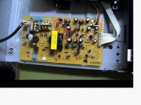
Assyst1606 said:Hi, i have read thru'. I'm not good at this. Wonder if this resistor (circled in red) or those before the transformer belongs to the start up resistors? All the resistors look fine to me, no burn mark.
Maybe it's just a snubber resistor.Here's a hint,just look for a high value(usually a few hundred kiloohms) resistor that connected to the pin3(Vcc) of the IC.
pin1=ground
pin2=output
pin3=Vcc
pin4=feedback
ps: is this your switcher IC?http://www.fairchildsemi.com/pf/FS/FSDM0465RB.html
Possibly not this one but the more popular KA5L0380R.
- Status
- Not open for further replies.
- Home
- Source & Line
- Digital Source
- Sharp DVD player DV-740 gone bad