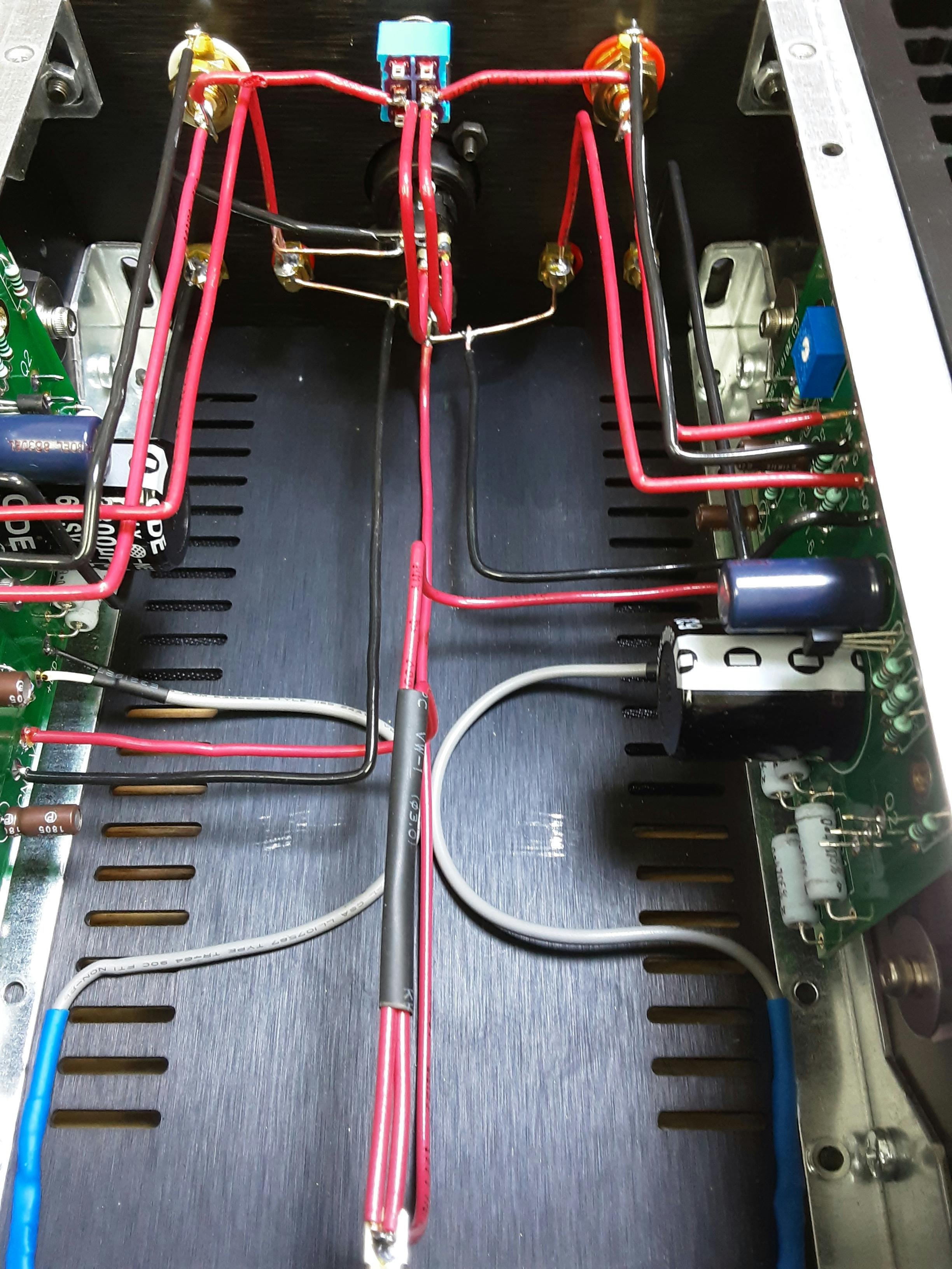
I see a lot of images of builds with sharp 90-degree bends of the internal wiring. It looks great, but is this bad practice from a technical point of view?
I'm not suggesting the electrons are going to have trouble turning the corner, more than you are deforming, if not damaging the wire and jacket.
Here is an image of what I am talking about. I know it will work, but would you be better off with a gentle curve?
I'm not suggesting the electrons are going to have trouble turning the corner, more than you are deforming, if not damaging the wire and jacket.
Here is an image of what I am talking about. I know it will work, but would you be better off with a gentle curve?
"Deforming the copper wire " ? ---every time a coil is wound for transformers/electric motors etc you are "deforming it " ,have a look at the manufacturing process of producing copper wire machines put the copper under great stress in the first place.
Your point would make sense in HF radio communication where at VHF /UHF bending wires or even earth returns ( short as possible ) can change the frequency of a tuned circuit .
But we are dealing with audio here 20Hz-20KHz , I realize some "audio " websites go into great detail as they say ---"yes I can hear the difference of Teflon covered wire etc " but for me that's leaving reality under the haze of smoke of a banned substance in my country.
Now if it was a case of discussing electron flow in a copper wire that's a different matter , I have built communication receivers and at HF in the first input stages then where and how a wire goes makes a big difference or if we were discussing earth returns in audio then routing takes on significance .
Any insulating material "stressed " out of shape can deteriorate long term but it depends on the chemical composition of the insulating material .
But here is the view of NASA -
NASA Parts Selection List (NPSL) - Wire Insulation Selection Guidelines
I would recommend more gentle bends. If you were to peruse the National Electric Code (it's a real page turner, trust me..😱) you will find that there are bend radius specifications based on the diameter of the wire. The reason is to not overstress the insulation. On the outer side of a bend, the insulation is stretched, and over time it might crack, exposing the conductor.
This is far more important for chassis wiring of the line in hot conductor.
Code is radius of curvature must not go below 5 to 8 diameters depending on the wire guage.. For typical wires we would use in a chassis, that's really not too bad, just don't overdo it
jn
This is far more important for chassis wiring of the line in hot conductor.
Code is radius of curvature must not go below 5 to 8 diameters depending on the wire guage.. For typical wires we would use in a chassis, that's really not too bad, just don't overdo it
jn
When looking at vintage gear PCBs all tracks appear to be rounded.
Now all tracks are sharp bended.
I presume it must be an improvement...
Now all tracks are sharp bended.
I presume it must be an improvement...
Improvement in space use. In a UHF tuner or something, and right angle turn is an inductor - at those freqs enough to detune it. At audio, it doesn't matter.
Though the heavy bus wire isn't insulated, look at how GR did it. Slight radius, but many 90 degree bends. Lasted more than 79 years and still going strong!
The GR 716-C Capacitance Bridge
The GR 716-C Capacitance Bridge
That photo - someone's obsessed with appearance, which does nothing for performance.
Yes.
Attachments
Would a round turn not be the same ? I mean tuner coils are also round.and right angle turn is an inductor
Perhaps newer software for calculating PCB coil dimensions assume them straight.
COils are round because they have multiple turns. Board design is a whole science unto itself, especially at high RF freqs. A sensitive trace might even have a grounded guard trace beside it to prevent it from interacting with others.
Diameter of a coil is a factor in determining its inductance, so a tight little corner has a smaller diameter than a sweeping curve.
Diameter of a coil is a factor in determining its inductance, so a tight little corner has a smaller diameter than a sweeping curve.
Also is there a EMI aspect to bends - for example on a PCB tracks are 45 degree or curved (in the case of digital timing delay tracks) but not 90?
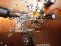
The messy surface mount would be something I'd end up doing 😀
The messy surface mount would be something I'd end up doing 😀
When I was at Uni, eons ago, I remember doing lab experiments on conductive paper with different shapes and measuring the field strengths at their boundaries.
IIRC, the 'sharp point' was the worst, i.e radiated the most. The radiated field reduced as the angle of the point got wider towards a straight line. Eventually with a pointed needle, you could ionise the surrounding air with enough dc voltage.
Going around corners using 45 degrees was a good compromise on PCB tracks if forced to us straight lines. Otherwise, use smooth curving tracks.
Cheers
Mike
Thanks everyone! Good info as always. Yes, intuitively, makes sense to not 'stress' things but in the context of this build it would be highly unlikely to cause any issues.
That photo - someone's obsessed with appearance, which does nothing for performance.
Yeah, but it just looks purdy.
Remember the wiring harnesses in QUAD 33 / 303?
I wouldn't worry about the 90 degree bends if no brute force was used. The wires will outlive the components anyway. Possibly the unsupported wires may cause stress fractures at the solder joints over time.
1 Pascal=94dB
1 Pascal=94dB
90 degree turns aren't much of an issue if at all at audio frequencies, but at microwave frequencies they would spray field all over the place. All a question of wavelength.
What does matter more is using twisted-pair for power wiring so that its not magnetically coupling mains hum into the box.
What does matter more is using twisted-pair for power wiring so that its not magnetically coupling mains hum into the box.
- Home
- Design & Build
- Construction Tips
- Sharp bending of internal wires. Bad practice?