Hey diyA - I posted my completed 45 parafeed amplifier recently, this was the one that came before it, my first design-to-build amplifier. Again, nothing innovative, but I am proud 🙂 I spent 2-3 months planning and learning about tube design, then built it (except for chassis, which was made by Landfall Systems). I am still relatively new to the forum, so not sure if many share their completed work, but what the heck.
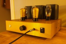
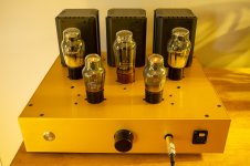
It is a two-stage SET, MH4 / REN904 (and equivalents) input with cascode MOSFET CCS load. Output tube is the indirectly heated version of the 6B4G, the 6A5G with cathode bias. Output transformers are Lundahl LL1620 60mA.
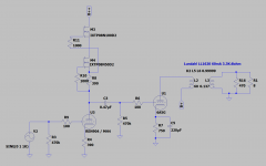
Here is the amplifier schematic.
And power supply.
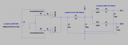
Since this was my first design, there are some aspects of the power supply that are a bit...unconventional. Rectifier is a hybrid diode-tube full-wave bridge using the U18/20 4V rectifier. There is also a combo rectifier socket - it can use 5Z3 as well. It is a CLCLC supply using 27H of Lundahl chokes per channel. The unconventional aspect is the driver stage is the first tap in the supply given the higher B+ requirement of the CCS load. A somewhat significant amount of internal restisance was added (1.6K per channel) to drop the voltage for the 6A5G B+, which has been split into two separate rails. The sound is very good, so the added resistance doesn't seem to have had a deleterious effect.
Bias points.
MH4 cathode: 2.44V
MH4 plate to cathode: 184.4V
6A5G cathode: 45.5V
6A5G plate to cathode: 251.5V
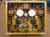
Here is the interior. May be going back in to better optimize some wiring.
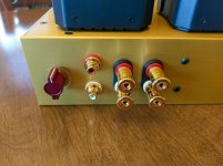
Rear I/O with Goldpoint switch for the headphone output.
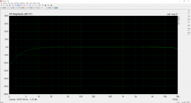
Here is the frequency response, down about 1.7dB at 20kHz, which might be investigated.
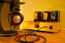
Some photos with my headphones, before the amp was placed in my stereo.
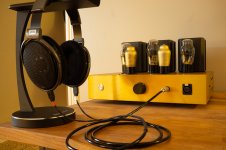
It will be driving a pair of 98dB/W stand-mount Omega speakers and a pair of 92dB/W Snell J/II speakers in my smallish room.
Thanks for looking!


It is a two-stage SET, MH4 / REN904 (and equivalents) input with cascode MOSFET CCS load. Output tube is the indirectly heated version of the 6B4G, the 6A5G with cathode bias. Output transformers are Lundahl LL1620 60mA.
Here is the amplifier schematic.

And power supply.

Since this was my first design, there are some aspects of the power supply that are a bit...unconventional. Rectifier is a hybrid diode-tube full-wave bridge using the U18/20 4V rectifier. There is also a combo rectifier socket - it can use 5Z3 as well. It is a CLCLC supply using 27H of Lundahl chokes per channel. The unconventional aspect is the driver stage is the first tap in the supply given the higher B+ requirement of the CCS load. A somewhat significant amount of internal restisance was added (1.6K per channel) to drop the voltage for the 6A5G B+, which has been split into two separate rails. The sound is very good, so the added resistance doesn't seem to have had a deleterious effect.
Bias points.
MH4 cathode: 2.44V
MH4 plate to cathode: 184.4V
6A5G cathode: 45.5V
6A5G plate to cathode: 251.5V
Here is the interior. May be going back in to better optimize some wiring.

Rear I/O with Goldpoint switch for the headphone output.

Here is the frequency response, down about 1.7dB at 20kHz, which might be investigated.

Some photos with my headphones, before the amp was placed in my stereo.


It will be driving a pair of 98dB/W stand-mount Omega speakers and a pair of 92dB/W Snell J/II speakers in my smallish room.
Thanks for looking!
Last edited:
Is that frequency response with a load on the amp? (an 8 ohm load)
Often times with SE transformers you can trade flat response past 20kHz for far better low frequency response. That's a trade I'm always willing to make.
Often times with SE transformers you can trade flat response past 20kHz for far better low frequency response. That's a trade I'm always willing to make.
It is from the headphone output, so a 9.1ohm resistor across the output in parallel with a 300ohm dummy load. So roughly 8.8ohms.
I have a switchable headphone dummy load I put together, need to finish my 4/6/8/16ohm dummy for speaker measurements.
I can't hear past 17kHz anyway, so I'll take the bass 😀
I have a switchable headphone dummy load I put together, need to finish my 4/6/8/16ohm dummy for speaker measurements.
I can't hear past 17kHz anyway, so I'll take the bass 😀
That's a great looking amp. Nice neat work! How's it sound?
Thank you! It sounds very good. Granted, this is my first DIY SET amplifier, so perhaps bad sound is the exception, not the norm? I had hoped for "good" sound, wasn't prepared for how good it is. The soundstage is expansive, very airy and detailed with great low end. The only negative is there is measurable 60Hz noise, although I cannot hear it. I believe it is a side effect of the 6A5G tubes - the heaters are center-tapped and connected to the cathode. The purpose of these indirectly-heated tubes was to reduce the hum of the 6B4G when AC heated. It is very much inaudible on speakers, I am going to go back in and see if I can minimize it, taking measurements always makes more work, would not have even known 😛
Nice looking build. I would try put in a little NFB just to test if things get better or worst.
I'll give that some thought, thanks for the suggestion.
I would look at a few things before I would apply any negative feedback.
1. Harmonic Distortion at 1 kHz, at 1 Watt
2. Shape of 20 Hz sine wave, at 1 Watt.
3. Square Wave response
1kHz square, look at the downward slope.
10kHz, look at "ringing", overshoot, undershoot.
4. Volts peak to peak just before clipping at 1kHz.
Only after you do these tests (to set up a Benchmark), should you apply some negative feedback.
That way, you will have several important Benchmarks to compare to: The before and after when you apply negative feedback.
You may be surprised.
If you want to try negative feedback, may I suggest changing R5 to 270 Ohms, and put a 100 Ohm resistor from the bottom of R5 to ground (cathode, 270 Ohm, 100 Ohm, ground).
Use a feedback resistor from the 8 Ohm tap, back to the junction of the new 100 Ohm resistor and bottom of R5.
If I can guess, the following may be true when you apply negative feedback:
# 1 may get better.
# 2 may get worse
# 3 may get worse
# 4 may stay the same
You may, or may not like the sound with negative feedback.
I bet the amplifier performs very well just the way it is.
Last edited:
LOrdGwyn, Very build! Is the chassis custom made or is it something that can be ordered. If so, can you share a source, I sure like the chassis quality. Mickeystan
I would look at a few things before I would apply any negative feedback.
1. Harmonic Distortion at 1 kHz, at 1 Watt
2. Shape of 20 Hz sine wave, at 1 Watt.
3. Square Wave response
1kHz square, look at the downward slope.
10kHz, look at "ringing", overshoot, undershoot.
4. Volts peak to peak just before clipping at 1kHz.
Only after you do these tests (to set up a Benchmark), should you apply some negative feedback.
That way, you will have several important Benchmarks to compare to: The before and after when you apply negative feedback.
You may be surprised.
If you want to try negative feedback, may I suggest changing R5 to 270 Ohms, and put a 100 Ohm resistor from the bottom of R5 to ground (cathode, 270 Ohm, 100 Ohm, ground).
Use a feedback resistor from the 8 Ohm tap, back to the junction of the new 100 Ohm resistor and bottom of R5.
If I can guess, the following may be true when you apply negative feedback:
# 1 may get better.
# 2 may get worse
# 3 may get worse
# 4 may stay the same
You may, or may not like the sound with negative feedback.
I bet the amplifier performs very well just the way it is.
Thanks, 6A3. Truthfully, I am very happy with the sound and not very interested in applying negative feedback. I won't rule it out, but the amp is very performative as is 🙂 I have not gone through the full gamut of testing just yet, mostly because I jumped immediately into a second build, but I will be sure to get a benchmark if I were ever to consider NFB.
LOrdGwyn, Very build! Is the chassis custom made or is it something that can be ordered. If so, can you share a source, I sure like the chassis quality. Mickeystan
Thanks, Mickey. It is custom through the company Landfall Systems. Dave is a great guy to work with. Not necessarily cheap, but the quality is very good, he will machine to your specifications and then has it anodized at a shop local to him, silver and black being cheaper, he had to go to a different shop to get gold, but he made it happen!
Last edited:
Hey diyA - I posted my completed 45 parafeed amplifier recently, this was the one that came before it, my first design-to-build amplifier. Again, nothing innovative, but I am proud 🙂 I spent 2-3 months planning and learning about tube design, then built it (except for chassis, which was made by Landfall Systems). I am still relatively new to the forum, so not sure if many share their completed work, but what the heck.
View attachment 843065 View attachment 843066
It is a two-stage SET, MH4 / REN904 (and equivalents) input with cascode MOSFET CCS load. Output tube is the indirectly heated version of the 6B4G, the 6A5G with cathode bias. Output transformers are Lundahl LL1620 60mA.
Here is the amplifier schematic.
View attachment 843069
And power supply.
View attachment 843070
Since this was my first design, there are some aspects of the power supply that are a bit...unconventional. Rectifier is a hybrid diode-tube full-wave bridge using the U18/20 4V rectifier. There is also a combo rectifier socket - it can use 5Z3 as well. It is a CLCLC supply using 27H of Lundahl chokes per channel. The unconventional aspect is the driver stage is the first tap in the supply given the higher B+ requirement of the CCS load. A somewhat significant amount of internal restisance was added (1.6K per channel) to drop the voltage for the 6A5G B+, which has been split into two separate rails. The sound is very good, so the added resistance doesn't seem to have had a deleterious effect.
Bias points.
MH4 cathode: 2.44V
MH4 plate to cathode: 184.4V
6A5G cathode: 45.5V
6A5G plate to cathode: 251.5V
Here is the interior. May be going back in to better optimize some wiring.
View attachment 843067
Rear I/O with Goldpoint switch for the headphone output.
View attachment 843068
Here is the frequency response, down about 1.7dB at 20kHz, which might be investigated.
View attachment 843075
Some photos with my headphones, before the amp was placed in my stereo.
View attachment 843071
View attachment 843072
It will be driving a pair of 98dB/W stand-mount Omega speakers and a pair of 92dB/W Snell J/II speakers in my smallish room.
Thanks for looking!
Nice! I envy people that can crank these out. I start changing too many things along the way and going into loops! But I enjoy project posts the most.
L0rdGwyn,
Great!
I have built many 2 stage SE amplifiers with DHT outputs, 45, 2A3, 300B, 6B4G, and 6A3.
If I had a 6A5G, I would try that too.
I did not, and would not use negative feed back on any of those amplifiers.
Great!
I have built many 2 stage SE amplifiers with DHT outputs, 45, 2A3, 300B, 6B4G, and 6A3.
If I had a 6A5G, I would try that too.
I did not, and would not use negative feed back on any of those amplifiers.
Last edited:
Very nicely executed.
Thanks very much!
L0rdGwyn,
Great!
I have built many 2 stage SE amplifiers with DHT outputs, 45, 2A3, 300B, 6B4G, and 6A3.
If I had a 6A5G, I would try that too.
I did not, and would not use negative feed back on any of those amplifiers.
Duly noted! I would like to use the 801A as power output in my next amplifier, I have collected a set, although there is no timeline, I need a break after building two amplifiers in a row.
I also like the look of oyur work. Congrats!
Did you pull these Telefunken REN904's from German Volksempfaengers 😀?
Best regtrds!
Did you pull these Telefunken REN904's from German Volksempfaengers 😀?
Best regtrds!
I also like the look of oyur work. Congrats!
Did you pull these Telefunken REN904's from German Volksempfaengers 😀?
Best regtrds!
HA! I did not, but perhaps someone did 😀 some came in original boxes. These are very nice sounding tubes.
This datasheet from a NOS box I have not seen anywhere on the internet.
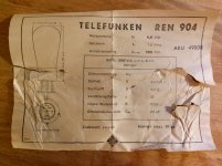
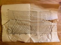
These are exactly two pages of a TELEFUNKEN tube data book from 1934 that I own 😉. I've got it from a schoolfrid whose father run a TV and radio service shop in the 1970ies.
Best regards!
Best regards!
- Home
- Amplifiers
- Tubes / Valves
- Sharing My First Scratch Build - REN904/MH4 Input, 6A5G Output SET