grovegardner,
You give me food for thought . . . trying push pull and a common cathode resistor without a bypass cap.
I need to think more about the transition region from class A to class AB; and then the
possibility of softer clipping too.
I have some ProAc speakers.
What ProAc model do you have?
I have the original Response 2's.
I have done the experiment to see the transition into cutoff of a PP output. I was testing the marketing of many EL84 PP outputs being "class A" in guitar amps. I reduced the plate voltage with a dropping resistor in the PS to see if I could (duel adjustable bypassed cathode) bias into class A. Could not get close. I call BS on all PP "Class A" guitar amps. I have yet to see any proof that a commercially-available one truly exists. Show me the traces and I’ll believe it.
Although many "PP Class A” outputs are likely class AB, the premise of the OP included Class A. Accepting vs not accepting that premise, I think, leads to different answers to the OP's question.
Or perhaps the premise is not possible since the “…..classic 2A3 SE operating point….” is “colder” than center biased, and thus class AB in a PP?
Totally agree... It's all marketing hype BS.. ... It is well known that these "Classic PP Class-A" Guitar amps are just very hot biased Class AB amps... on the verge of Class-A ....most of these amps are on the verge of melt-down... pushing the tubes past their limits... Once these amps age with all that heat...they start falling apart .. A lot of this subject is old hat on the pros and cons of by-pass caps ..ect.... I looked at this stuff and experimented with this in the late 70's.... while the old timers then would chuckle...I guess each generation has to re-invent the wheel...LOL
I beleive the single ended amp is class A as long as you do not cause the plate current to go to zero. Clipping on the max current is one thing. But clipping on the min current and going to zero is another. Right?
I also believe a push pull amp is in class A until one tube no longer responds to the signal voltage on its grid (usually at or near zero plate current for that tube). Beyond this point, we seem to be in class AB. Right?
I also believe that there are engineering definitions. But not all marketing groups strictly use those definitions; they may want to tell half the truth to increase their market size. For example, they may call the push pull amp class A (it is ~ half the time). Right?
Last edited:
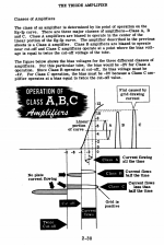
Class A operation is simply when the devices conducts 100% of the time. If a device "cuts off" in a push pull design, it ceases class A and enters class B since only one device is conducting. This is where we get class AB. Both modes are possible depending on the signal level. A class B amp is biased at cut off, so (in a perfect world, tubes are NOT perfect by any means) the idle current would be 0 mA. In most tube equipment I've seen it's at least 10 mA though, but most people would call that a class B amplifier. 🙂
This is my favourite illustration of it...
This is my favourite illustration of it...
Attachments
Last edited:
I could not have said it better.
Many if not all the McIntosh amps were class B. They had multiple primary windings, and cathode feedback at 1:1. The drivers were bootstrapped to get enough voltage swing (the cathode moved as much as the plate).
Class C is a great thing for many RF amplifiers. AB is another mode for RF amplifiers.
Many if not all the McIntosh amps were class B. They had multiple primary windings, and cathode feedback at 1:1. The drivers were bootstrapped to get enough voltage swing (the cathode moved as much as the plate).
Class C is a great thing for many RF amplifiers. AB is another mode for RF amplifiers.
http://sportsbil.com/other/Basic Electronics, Volumes 1-5, (1955).pdf
Shared before, but shared again... And obviously, class C is rubbish (for audio)...
Shared before, but shared again... And obviously, class C is rubbish (for audio)...
Last edited:
I assumed the OP was referring to sharing a cathode resistor between two tubes in a PP circuit.
Yep. And I do have a similar circuit to yours that allows me to balance the plate currents.
My bias point is 260V/60 ma with a 5k/8 ohm plate to plate output transformer
VinylSavor: Tube of the Month : The 2A3 (scroll down).
I had assumed this was cut-and-dried Class A, no?
Last edited by a moderator:
Many if not all the McIntosh amps were class B.
I've seen this stated a lot but I've analyzed bias points on the amps and they seem to be 50mA bias for KT88, maybe a little less for the earlier 6L6 amps. Seems to be too much current to qualify as "class B" to me.
SpreadSpectrum,
I stand corrected. 50mA for a KT88 is not class B.
I re-viewed one of those 6L6GC push pull McIntosh amps.
I saw some interesting things.
The output screens were tied to the opposing output plates.
Positive feedback
When the output tube cathodes have to swing as many volts as the output tubes plates do, you have to use unusual methods.
The cathode follower that drives the output tube control grid, has its plates tied to the output tube plates.
Bootstrapping, positive feedback.
The driver tubes had their plate load resistors getting their 'B+' from the output tube plates.
Bootstrapping, positive feedback.
I think the real 'secret' to making the McIntosh amps work real well, was partly the unusual circuits, and partly the quality of the output transformers.
Last edited:
6A3sUMMER,
I've done one with the Plitron McIntosh-style transformers without a bootstrapped driver. It is doable. You just have to figure out a way to get a driver to give ~160Vrms at low distortion. There are ways without the positive feedback.
And if you look closely at the screen connections in the output stage, the connection of the screen to the opposite tube plate applies no net signal to the screen, that is to say the voltage between the screen and the cathode of any output tube is constant. For sure, the cathode and screen are moving all around but there is no AC voltage between the two.
You have pentode operation at AC, with no signal voltage applied to the screens. Pretty awesome IMHO.

SpreadSpectrum,
That was 'Impulsive' of you to figure out how to get linear 160Vrms from a driver.
I said Impulsive to you respectively, but I intended the pun. (I used to give spectrum analyzer support on all kinds of signals). What is in a name? You got a good one.
And I need to look more carefully; the fact that the screen to cathode voltage was not changing went right over my head. Once you told me, I did not even have to go back to the schematic to see it in my head.
Thanks!
The more I look at old engineering practices, the more I see the old geniuses.
At the time I picked my name I was doing a lot of RF measurements. 😉
I am curious as to where the McIntosh amps got their reputation for being Class B from, though. I've seen it in a lot of literature.
I'm speculating here, but I think that while the transformer design makes Class B operation a possibility due to the avoidance of notch distortion, other performance considerations come into play. I have done Zout measurements that show that Zout goes down fast as idle current increases. I would guess that if you ran these amps at 10mA, the Zout would triple or more. That's probably reason enough to crank up the idle current a bit, and a KT88 is still barely breaking a sweat at 50mA.
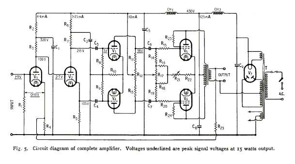
Thanks for this reminder of the Williamson circuit, which I should have referenced much earlier in the thread.No, I have not done a study of distortion characteristics, except with my ears. 🙂. I prefer my Williamsons without the bypass caps. I assume with my old ProAcs they are probably pushing the limits of 12 watts with some music.
I assumed the OP was referring to sharing a cathode resistor between two tubes in a PP circuit.
Of course, it uses a shared, unbypassed cathode resistor and it is one of THE classic circuits.
Comments on its operation?
The McIntosh amps are AB not B..... I wound many of those OT's and built a number of the amps... Yes, the key to linearity is to maintain a constant gm ...Since gm is all over the place during normal dynamic operation... Not just the Screen an Cathode on Parallel windings but the PLATE as well..the net AC looks to be zero....thus you get a constant gm...and very linear performance.... SO the tubes looks to be a perfect CCS with constant gm... How on earth did this this thread end up on McIntosh ???? LOL
Last edited:
Thanks for this reminder of the Williamson circuit, which I should have referenced much earlier in the thread.
Of course, it uses a shared, unbypassed cathode resistor and it is one of THE classic circuits.
Comments on its operation?

Sheer musicality, and *bandwidth*. Build the Musician's Amplifier with Heyboer S-265-Q clones and you'll never go back to PP DHT's without feedback. ;-)
I wouldn't say that it's one of, rather that it's THE last of the classic circuits. Like Beethoven was the last of the classic European composers and the first of the Romantics or Einstein was the last classical physicist and the first quantum physicist, everything changed immediately after DTN Williamson.Thanks for this reminder of the Williamson circuit, which I should have referenced much earlier in the thread.
Of course, it uses a shared, unbypassed cathode resistor and it is one of THE classic circuits.
Comments on its operation?
Its operation is lightly loaded class-A triodes so doesn't need a cathode resistor bypass cap. It doesn't really need loop feedback if operated conservatively.
All good fortune,
Chris
How on earth did this this thread end up on McIntosh ???? LOL
He sneaks his way into all kinds of threads...
Sorry for the diversion.
- Status
- Not open for further replies.
- Home
- Amplifiers
- Tubes / Valves
- Shared cathode resistor - always sub-optimum