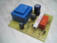
Made a simple and effective Soft Start Module for my 800VA Transformers for my ZAP Pulse amplifiers.
Works great. 8 seconds for the Tx to build up the inductionfield and it stops me resetting main fuses and there is no large hummm when the amplifier starts.
All safe stuff with low 12 V DC as well
FYI 🙂
Doede
Works great. 8 seconds for the Tx to build up the inductionfield and it stops me resetting main fuses and there is no large hummm when the amplifier starts.
All safe stuff with low 12 V DC as well
FYI 🙂
Doede
Attachments

Hi Doede:
I presume there will be a kit offer for the lazy 😉
It looks smaller than ampslab's offer wich works very well.
http://www.ampslab.com/inrush_schematics.htm
Isn't 8'' too much?
Thanx
Mauricio
I presume there will be a kit offer for the lazy 😉
It looks smaller than ampslab's offer wich works very well.
http://www.ampslab.com/inrush_schematics.htm
Isn't 8'' too much?
Thanx
Mauricio
Guys,
Nice circuit. However there must be more distance on the PCB between the copper tracks of the circuit what is conencted to mainsvoltage and the low voltage.
6mm is the real minimu,m better is to go for 8mm.
Below 6mm you can have a dangerous situation!!
Regards,
Jan-Peter
Nice circuit. However there must be more distance on the PCB between the copper tracks of the circuit what is conencted to mainsvoltage and the low voltage.
6mm is the real minimu,m better is to go for 8mm.
Below 6mm you can have a dangerous situation!!
Regards,
Jan-Peter
J-P, you are right in general but not in this case. As long as Doede only uses his 12 V to drive the relay he must consider insulation between 230 V parts at the pcb and 230 V towards his chassis. So 8 mm from screwholes to any traces must he consider. I don't like the 230 V connection to the transformer, too short crepage distances. I use 3-pole 5 mm grid and uses only pin 1 and pin 3. Pin 3 is unconnected.Jan-Peter said:Guys,
Nice circuit. However there must be more distance on the PCB between the copper tracks of the circuit what is conencted to mainsvoltage and the low voltage.
6mm is the real minimu,m better is to go for 8mm.
Below 6mm you can have a dangerous situation!!
The smoothing needs only to be 100-220 uF for driving a relay. 2200 uF makes only the transformer warm.
The 230 V traces should withstand 10 A fuse so a little bit wider would be good. 100-150 mil wide and 70-105 um thick.
My softstarter can be found here if you don't know it already. I use the "dangerous" transformerless but reliable solution.
Kenshin said:Why do it on the mains?
It could also be done on the second stage. (Large current relay needed)
Hi
Could you explain us why the inrush current appears, and why it also can be solved at the secondary ?
cheers
Thanks for the 230 Volt inputs. It will for sure not get VDE proof 😀
any way, if this is the most unsecure thing I will see in DIY, I will change it
On the other question, this is not for sale and no kit for the reasons already mentioned before ....
take care
doede
PS: Guido is right. (although is not realy stating his point, but I have assumed on the way he puts his question this is the case...) Inrushcurrent is coming from the primary winding only. Also a without any secundary connection the fuse will trip if the transformer is large enough. I am also curious how this will work on the secondary ...
Kenshin isn't aware of the whole picture, therefore his suggestion but you, Guido, doesn't need any explanantions, right?
Kenshin, the transformer itself even without any load will have huge inrush currents.
Kenshin, the transformer itself even without any load will have huge inrush currents.
peranders said:Kenshin isn't aware of the whole picture, therefore his suggestion but you, Guido, doesn't need any explanantions, right?
Kenshin, the transformer itself even without any load will have huge inrush currents.
I tried to let Kenshin answer the question, best way to learn.......
cheers
On the other question, this is not for sale and no kit for the reasons already mentioned before ....
I started to search for the parts at RS-online.com. I only found Finder relay 40.61.9, rated for 12VDC/16A. I presume it would do.
Also, BC550C can be found for between 0.6 and 19 pounds sterling! 😱
I hope the cheapest one will be OK.
BC550C costs a couple of cents and I can't really understand where 19 punds come from.
BTW, I have a couple of hundreds of BC560C/BC550C
BTW, I have a couple of hundreds of BC560C/BC550C
maxlorenz said:
I started to search for the parts at RS-online.com. I only found Finder relay 40.61.9, rated for 12VDC/16A. I presume it would do.
Also, BC550C can be found for between 0.6 and 19 pounds sterling! 😱
I hope the cheapest one will be OK.
The one at 19 pounds is for a reel of 1000 pieces...
There is another simpler way to do the same, that works just as well and is cheaper, just if anyone is interested:
The low voltage transformer can be eliminated and build a typical transformerless power supply based on a 0.68uF to 1uF / 400V capacitor (mains rated), and a small resistor in series, then all you have to do is rectify that and put a 12V zener to limit the output voltage, as well as a large enough filter capacitor.
Once you have 12V at around 40mA, you can simply connect the relay, (the delay will be the produced by the filter capacitor charge time), or you can put a RC circuit biasing a transistor that activates the relay. All that can be done in a much smaller space.
I usually do this and I haven't had any failure, it works very well. After some years, I saw an article at Elektor with a very similar proposal.
Best regards
Pierre
Yes Pierre, I also use the same transformerless solution to power little microcontoller boards and it works rather well, but if someone wish to try such a solution, just keep in mind to buy a
X or X2 capacitor, standard 400V cap is not enough secure on mains (I experienced twice a blown cap after several months of daily use.. and nothing since i replaced it by X2 caps).
Regards
Eric
X or X2 capacitor, standard 400V cap is not enough secure on mains (I experienced twice a blown cap after several months of daily use.. and nothing since i replaced it by X2 caps).
Regards
Eric
Cheaper ???
Just to clarify, this is NOT an expensive solution...
I paid for all the part per assembly at Reichelt 5,50 Euro 😎
The transformer costs only 1,50 Euro....
I Guess a high voltage Foil capacitor will cost more
regards
doede
PS: The relay is 16A indeed, but has 2 contacts, makes it 32A
Just to clarify, this is NOT an expensive solution...
I paid for all the part per assembly at Reichelt 5,50 Euro 😎
The transformer costs only 1,50 Euro....
I Guess a high voltage Foil capacitor will cost more
regards
doede
PS: The relay is 16A indeed, but has 2 contacts, makes it 32A
- Status
- Not open for further replies.
- Home
- Amplifiers
- Class D
- Share my Soft Start Module for large Transformers