I'm having a crack at rod elliots car supply and built the controller circuitry. I hooked the outputs up to a scope to see if it was working and i noticed some pretty nasty ringing on the switching square waves. Is this normal??
Do you have the 0.1uF cap across pins 12 and 13 of the IC (as close to the IC as posible?)
Is this just the SG3525 by it's self or do you have a transformer hooked up?
If you have poor grounding on your scope probe you'll get the same thing.
Is this just the SG3525 by it's self or do you have a transformer hooked up?
If you have poor grounding on your scope probe you'll get the same thing.
I took these measurements at the out puts of the sg3525. No output devices were connected. I already tried a capacitor it made no difference. I measured it with the probe grounded and then floating and it made no difference.
Cheers, steve
Cheers, steve
Can you post an image of what your getting, it will help us help you out better.
BTW which schematic are you using? Sergio's (first schematic?) or Rod Elliott's (second schematic?)
You should get a different wave form (mostly ringing) when the ground is removed. If you get no difference with or with out, then I would say you have a grounding issuse with either your scope or your current setup.
BTW which schematic are you using? Sergio's (first schematic?) or Rod Elliott's (second schematic?)
I measured it with the probe grounded and then floating and it made no difference
You should get a different wave form (mostly ringing) when the ground is removed. If you get no difference with or with out, then I would say you have a grounding issuse with either your scope or your current setup.
rod elliott smps is great!!
Hi SMPS builders
I Build many smps rod elliott project. It´s working very good. I have a SG3525 + 12 FTP50N06 mosfet + 2 inches toroidal transformer/ input 12VDC- output +63/-63VDC. I can post pics for you, ok?
I build other SMPS with 115/230VAC and +80/-80VDC for my power amp. It´s very good the performance.
Thank you very much.
CHACALPOWERS
Hi Sach..... Please do, and if possible, the PCB layout too. I am trying to build one to power all my power amps for my car......
Getting there!!!
I filtered out the noise with some capacitors.
Built the mosfet power side of the circuit and wound a small toroidal transformer.
I havent got the high speed rectifier diodes but i still ran a few tests.
I hooked up the supply to a 13.8v 30a bench supply and loaded it down with a 16 ohm dummy load across the whole secondary.
I get around 70v p-p with it loaded down.
When loaded it sucks around 10A from the bench supply
I'm pretty happy with this so im gonna design a pcb for this and post it when its complete.
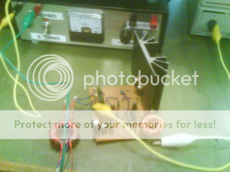
I'll post pics soon of my prototype... 10 amps of current through a veroboard....
I filtered out the noise with some capacitors.
Built the mosfet power side of the circuit and wound a small toroidal transformer.
I havent got the high speed rectifier diodes but i still ran a few tests.
I hooked up the supply to a 13.8v 30a bench supply and loaded it down with a 16 ohm dummy load across the whole secondary.
I get around 70v p-p with it loaded down.
When loaded it sucks around 10A from the bench supply
I'm pretty happy with this so im gonna design a pcb for this and post it when its complete.
I'll post pics soon of my prototype... 10 amps of current through a veroboard....

Hey guitar_joe, 😀
a stable output waveform on a prototype is a good thing! Congratulations... 😉
As for the spikes and rounded edges of the output, this will likely change with faster diodes, preferrably ultra-fast/soft-recovery.
Rod Elliot implements 'snubbers' on the primary as R1/R2 and C1/C2, respectively. On the secondary he puts C7/C10 for HF rejection.
But as no two handmade toroids are the same, I recommend you re-calculate these snubbers, as they will have unneccessary power loss (and low influence on filtering) when set for a different MOSFET/toroid/diode arrangement.
Jim Hagerman wrote a very comprehensive paper about it.
Cheers,
Sebastian.
Been ages since i posted on this thread. Finished building it and it works great.
Using a bunch of to220 dual diode schottkys for the rectifiers getting +/- 30 dc. Good project, learnt a bit about smps building this
Using a bunch of to220 dual diode schottkys for the rectifiers getting +/- 30 dc. Good project, learnt a bit about smps building this
iwould love to get into something like this. premature in the luikes of electtronics design etc. have access to some equipment cheap. any suggestions as to a project to start out with>? novice,remember? and i will do the research as to what i should get for tools.
All u need is a multimeter, a high current 12v supply and or a car battery - WITH A FUSE lol. a scope is pretty essential too.
I read the esp doc project 89 and learnt heaps on it.
I read the esp doc project 89 and learnt heaps on it.
- Status
- Not open for further replies.
- Home
- General Interest
- Car Audio
- SG3525 switchmode psu