I am aiming to prepare a somewhat special pair of parafeed (PF) amps for the purpose of extending the range of output transformer (OPT) testing that has been discussed in another thread (Measurements on output transformers for the Williamson amp).
Patrick (Turner Audio) passed away early this month and I had been in sporadic communication with him for years, and most recently emailed him about a test amplifier setup he had made decades ago to test the performance of output transformers. So with a sad heart I will continue on with making a somewhat similar test amplifier that hopefully can apply an acceptably low distortion sinewave to an OPT, but with sufficiently high signal voltage to emulate up to about 15W in to a 10kohm PP OPT in a class A amplifier, and use a modern soundcard and software tool to characterise the frequency response and distortion of such an OPT. I'm piggy-backing on what Patrick seems to have prepared, which was a pair of PF amps using 6CM5 in triode-mode, and with sufficient feedback to achieve a stable test bandwidth from about 20Hz to upward of 1Mhz, and at low distortion (eg. circa 0.1%).
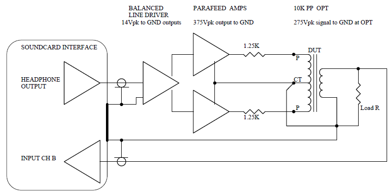
As shown in the diagram above, the OPT DUT is driven by the pair of PF amps in a balanced configuration with the B+ (CT) primary winding node of the OPT grounded, such that each PF amp is loaded by just half the PP primary winding. In addition each amp has a resistor inserted between the PF coupling cap and the OPT primary anode tap so as to be equivalent to an output stage driving tube Ra (for the Williamson the test originally used 1.25k to be equivalent to the KT66 anode output resistance). The remainder of the test jig is already set up and has been used for OPT testing at low signal voltage (as per the thread link above).
I'm not aiming for each amp to achieve a 1Mhz top end bandwidth for a number of reasons, but as this is a test setup I do need each amp to aim for as low a phase shift as practical down at the 20Hz end, and likely going up through 100kHz, as well as negligible amplitude change. As part of a test rig using modern software, any phase shift of the test rig (that will include the PF amps, but not the OPT DUT) can be automatically 'calibrated out' by a loopback test, leaving just the phase response of the OPT being tested in the measurement.
The output power target is to get close to 15W in to a 10kPP OPT that has a matched secondary resistive loading. Given each PF amp is driving only half the primary, that implies a 2k5 load on each amp. But each PF amp is also driving the OPT through an additional series resistance of circa 1.25k, to make a total PF amp loading of 3.75k. 15W into a 2.5k load would indicate a signal swing of 275Vpk, but that increases to 375Vpk at the PF amp output due to the added series 1.25k.
The 6CM5 was and is both common and cheap here in OZ, and many have used it for audio applications including Patrick who ran it in triode mode at up to 375V Vak idle, and appears to have used it in his custom test amp. I have a large batch of them so initially for this application I will use them rather than the likes of 6L6GC etc that I have fewer of, but I can foresee that the 6CM5 is likely not going to achieve 15W where I want it, so this test jig may have to graduate over to 6L6GC for Rev 2 (if I get that far). The 6CM5 in triode mode has an Ra of circa 750 ohm, and I can easily use 2 in parallel.
To keep phase shift as low as practical at a 20Hz low frequency end each PF amp output is likely to need circa 100uF of coupling cap. That is easy to achieve with e-caps, although I have sufficient metallized poly caps with at least 500Vdc rating to integrate in with the e-caps if needed.
Each main PF choke needs to be at least 30H to allow operation down to 20Hz, and preferably around 50-60H. Although that choke can be a series connection of whatever chokes are available, each choke needs to have a suitably low DCR/Henry ratio along with a high enough Vac and DC current capability. I can presently get to 30H, but need to seek out some more boat anchors.
This is just a test amp so will be nothing pretty and will use a large derelict amp chassis and I have a range of PT's to choose from. An aspect of this test rig is that the two PF amps will draw opposite phase signal currents from a common B+ supply, so the effective B+ load is going to be fairly constant over the range of test signal levels applied to a test OPT. Also I can arrange heater power and sockets for parallel 6CM5 to try and reduce effective Ra and hence move the main PF R-L corner frequency down as far as practical to reduce phase shift at 20Hz.
This will be my first foray in to PF amps so I have been trying to do sufficient background reading to confirm that using a PF amp in this test setup is worthwhile starting, and so far I can't rationalise an alternative way to achieve the OPT testing I am targeting. So I will continue on with preparations and get a draft schematic prepared and start to appreciate what performance can be achieved with what I've got to hand.
Ciao, Tim
Patrick (Turner Audio) passed away early this month and I had been in sporadic communication with him for years, and most recently emailed him about a test amplifier setup he had made decades ago to test the performance of output transformers. So with a sad heart I will continue on with making a somewhat similar test amplifier that hopefully can apply an acceptably low distortion sinewave to an OPT, but with sufficiently high signal voltage to emulate up to about 15W in to a 10kohm PP OPT in a class A amplifier, and use a modern soundcard and software tool to characterise the frequency response and distortion of such an OPT. I'm piggy-backing on what Patrick seems to have prepared, which was a pair of PF amps using 6CM5 in triode-mode, and with sufficient feedback to achieve a stable test bandwidth from about 20Hz to upward of 1Mhz, and at low distortion (eg. circa 0.1%).
As shown in the diagram above, the OPT DUT is driven by the pair of PF amps in a balanced configuration with the B+ (CT) primary winding node of the OPT grounded, such that each PF amp is loaded by just half the PP primary winding. In addition each amp has a resistor inserted between the PF coupling cap and the OPT primary anode tap so as to be equivalent to an output stage driving tube Ra (for the Williamson the test originally used 1.25k to be equivalent to the KT66 anode output resistance). The remainder of the test jig is already set up and has been used for OPT testing at low signal voltage (as per the thread link above).
I'm not aiming for each amp to achieve a 1Mhz top end bandwidth for a number of reasons, but as this is a test setup I do need each amp to aim for as low a phase shift as practical down at the 20Hz end, and likely going up through 100kHz, as well as negligible amplitude change. As part of a test rig using modern software, any phase shift of the test rig (that will include the PF amps, but not the OPT DUT) can be automatically 'calibrated out' by a loopback test, leaving just the phase response of the OPT being tested in the measurement.
The output power target is to get close to 15W in to a 10kPP OPT that has a matched secondary resistive loading. Given each PF amp is driving only half the primary, that implies a 2k5 load on each amp. But each PF amp is also driving the OPT through an additional series resistance of circa 1.25k, to make a total PF amp loading of 3.75k. 15W into a 2.5k load would indicate a signal swing of 275Vpk, but that increases to 375Vpk at the PF amp output due to the added series 1.25k.
The 6CM5 was and is both common and cheap here in OZ, and many have used it for audio applications including Patrick who ran it in triode mode at up to 375V Vak idle, and appears to have used it in his custom test amp. I have a large batch of them so initially for this application I will use them rather than the likes of 6L6GC etc that I have fewer of, but I can foresee that the 6CM5 is likely not going to achieve 15W where I want it, so this test jig may have to graduate over to 6L6GC for Rev 2 (if I get that far). The 6CM5 in triode mode has an Ra of circa 750 ohm, and I can easily use 2 in parallel.
To keep phase shift as low as practical at a 20Hz low frequency end each PF amp output is likely to need circa 100uF of coupling cap. That is easy to achieve with e-caps, although I have sufficient metallized poly caps with at least 500Vdc rating to integrate in with the e-caps if needed.
Each main PF choke needs to be at least 30H to allow operation down to 20Hz, and preferably around 50-60H. Although that choke can be a series connection of whatever chokes are available, each choke needs to have a suitably low DCR/Henry ratio along with a high enough Vac and DC current capability. I can presently get to 30H, but need to seek out some more boat anchors.
This is just a test amp so will be nothing pretty and will use a large derelict amp chassis and I have a range of PT's to choose from. An aspect of this test rig is that the two PF amps will draw opposite phase signal currents from a common B+ supply, so the effective B+ load is going to be fairly constant over the range of test signal levels applied to a test OPT. Also I can arrange heater power and sockets for parallel 6CM5 to try and reduce effective Ra and hence move the main PF R-L corner frequency down as far as practical to reduce phase shift at 20Hz.
This will be my first foray in to PF amps so I have been trying to do sufficient background reading to confirm that using a PF amp in this test setup is worthwhile starting, and so far I can't rationalise an alternative way to achieve the OPT testing I am targeting. So I will continue on with preparations and get a draft schematic prepared and start to appreciate what performance can be achieved with what I've got to hand.
Ciao, Tim
Last edited:
You are proposing a test for push pull transformers that will be used in push pull applications, Right?
What is your proposed output impedance of each parafeed amplifier that will drive the 1.25k series resistors?
Thanks.
What is your proposed output impedance of each parafeed amplifier that will drive the 1.25k series resistors?
Thanks.
Last edited:
The aim is to test PP transformers (the device-under-test DUT in the diagram) for use in PP class A operation (as per Williamson amp) - so no not trying to test OPTs for SE or parafeed type applications.
The PF amps are just a means to generate sufficient signal voltage to apply to the DUT, so as to emulate what the DUT is exposed to in a class A PP amp (except that DC imbalance in the DUT is by default equal to zero).
If the PF amps, and the rest of the test jig can be made 'blameless' (ie. low distortion) then a frequency spectrum sweep by the soundcard interface can effectively measure the response of just the OPT DUT.
Last edited:
Ah . . .
I guess you are using the output capacitors of the parafeed amplifiers to keep all DC off of the DUT primary windings.
So the parafeed output tube plate in parallel with the parafeed plate choke, and in series with the parafeed output capacitor are what the DUT sees when looking back at the drive signal.
I think I might be beginning to understand.
Thanks!
Yup - I wasn't too familiar with the standard output stage parafeed configuration a few months back, so it has been a bit of a crash course. Choke feed amp configurations are many and varied, but I am initially going to try just the simple triode output tube with a plate choke from B+, and the triode anode voltage signal fed through a coupling cap to a 'load' (which is typically an OPT for people with parafeed amps, but this test jig has a somewhat different 'load').