SET Rebuild (Odd behavior during testing)
I'm in the middle of re-building an amp I made a few years ago. New enclosure with better layout for improved wiring, a few tweaks and the replacement of unregulated DC filament supplies with Rod Coleman's DHT regulators for the output tubes.
A brief description of the amp: three-stage cap-coupled design (1/2 6SN7 - 6V6 - 300B/2A3) with fixed bias for the drivers and output tubes. Separate power supply chassis: two power transformers (input/drivers stage) (output stage), filament supplies for each output tube, and a shared supply for the input/drivers. The output stage is switchable between 300B and 2A3 (using a relay to switch between HV taps from the PT).
The schematic can be found here: Single-Ended 300B/2A3
I have a couple questions regarding implementation which I would like to address:
1. Proper cathode grounding of the DHT when using the current regulators and fixed bias.
2. Proper method to delay B+ of the output stage (to allow the regulators to rise to correct filament voltage).
In the past, I used the symmetrical grounding/fixed bias scheme as describe in Fig. A:
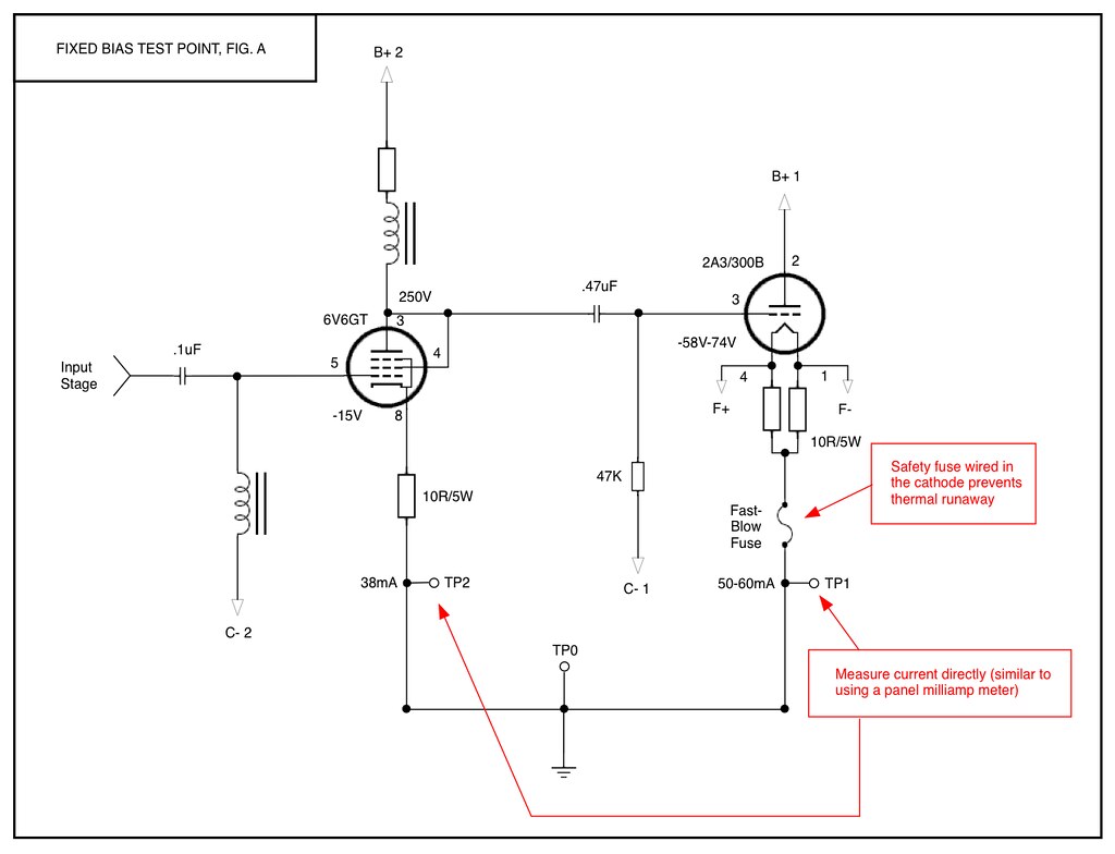
Two centering resistors soldered to the filament pins of the DHT to form a virtual centertap (similar to the classical bias scheme described in this linked pdf: http://jacmusic.com/techcorner/ARTICLES/APP-NOTES/AN07-How-to-bias-DHT-tubes-without-mistakes.pdf) then connected to a fast-blow fuse (to protect against thermal runaway) and then a test point to measure plate current between cathode to ground.
This worked well for me in the past.
The more common method to ground the cathode in a fixed bias scheme is described in Fig. B:

Here, the cathode is taken from one leg of the the DHT filament (either negative or positive, depending on the designer/builder preference). The test point is between the filament pin and the measuring resistor. And there is the absence of the protective fuse.
My preference is to use the classical bias scheme with two centering resistors (as described in Fig. A). But, Rod states in his instructions to v7 of his regulators to connect the cathode to the positive side of the filament. So, he seems to prefer the asymmetrical grounding scheme (Fig. B).
Q:If I use the bias scheme (Fig. A), will it interfere with the operation of the current regulation? I don't see how it could, but this is the first time I'll be using current regulation for filaments.
With respect to delaying the B+ to the output DHT when using current regulation for the filaments, I plan to use a "standby" switch wired in the centertap of the PT for the output stage.
Although the standby switch is the simplest approach (but, maybe not the best approach, as described elsewhere in these forums), I could use a timer network for the anode voltage.
Q: How long do I need to delay the B+ in order to allow the current regulators to stabilize? And can anyone recommend a low parts timer/delay for this purpose?
I'll have more questions, as I move forward with the build.
Here are the regulator boards adhered to their heatsinks:

(Note that once attached to the sides of the wood frame of the enclosure, the boards will be flipped upside down when the enclosure is right side up. Which is why I soldered the resistors "below" the boards as see in the photo.)
And the raw DC supply for the regulators:

Most of the raw DC supply will be wired in the power supply chassis. Only the final dropping resistors with Panasonic caps and the regulator boards will be housed in the signal chassis.
I created an album on Flickr to document the build: SET Build
Thanks in advance for any suggestions or comments!
I'm in the middle of re-building an amp I made a few years ago. New enclosure with better layout for improved wiring, a few tweaks and the replacement of unregulated DC filament supplies with Rod Coleman's DHT regulators for the output tubes.
A brief description of the amp: three-stage cap-coupled design (1/2 6SN7 - 6V6 - 300B/2A3) with fixed bias for the drivers and output tubes. Separate power supply chassis: two power transformers (input/drivers stage) (output stage), filament supplies for each output tube, and a shared supply for the input/drivers. The output stage is switchable between 300B and 2A3 (using a relay to switch between HV taps from the PT).
The schematic can be found here: Single-Ended 300B/2A3
I have a couple questions regarding implementation which I would like to address:
1. Proper cathode grounding of the DHT when using the current regulators and fixed bias.
2. Proper method to delay B+ of the output stage (to allow the regulators to rise to correct filament voltage).
In the past, I used the symmetrical grounding/fixed bias scheme as describe in Fig. A:
Two centering resistors soldered to the filament pins of the DHT to form a virtual centertap (similar to the classical bias scheme described in this linked pdf: http://jacmusic.com/techcorner/ARTICLES/APP-NOTES/AN07-How-to-bias-DHT-tubes-without-mistakes.pdf) then connected to a fast-blow fuse (to protect against thermal runaway) and then a test point to measure plate current between cathode to ground.
This worked well for me in the past.
The more common method to ground the cathode in a fixed bias scheme is described in Fig. B:
Here, the cathode is taken from one leg of the the DHT filament (either negative or positive, depending on the designer/builder preference). The test point is between the filament pin and the measuring resistor. And there is the absence of the protective fuse.
My preference is to use the classical bias scheme with two centering resistors (as described in Fig. A). But, Rod states in his instructions to v7 of his regulators to connect the cathode to the positive side of the filament. So, he seems to prefer the asymmetrical grounding scheme (Fig. B).
Q:If I use the bias scheme (Fig. A), will it interfere with the operation of the current regulation? I don't see how it could, but this is the first time I'll be using current regulation for filaments.
With respect to delaying the B+ to the output DHT when using current regulation for the filaments, I plan to use a "standby" switch wired in the centertap of the PT for the output stage.
Although the standby switch is the simplest approach (but, maybe not the best approach, as described elsewhere in these forums), I could use a timer network for the anode voltage.
Q: How long do I need to delay the B+ in order to allow the current regulators to stabilize? And can anyone recommend a low parts timer/delay for this purpose?
I'll have more questions, as I move forward with the build.
Here are the regulator boards adhered to their heatsinks:
(Note that once attached to the sides of the wood frame of the enclosure, the boards will be flipped upside down when the enclosure is right side up. Which is why I soldered the resistors "below" the boards as see in the photo.)
And the raw DC supply for the regulators:
Most of the raw DC supply will be wired in the power supply chassis. Only the final dropping resistors with Panasonic caps and the regulator boards will be housed in the signal chassis.
I created an album on Flickr to document the build: SET Build
Thanks in advance for any suggestions or comments!
Last edited:
Hi Jose! Good work with your clear schematic - with all the parts called out, we can see exactly what you have in mind.
My suggestions:
Connecting the filament to the "cathode" sense resistors:
Firstly, I should say that the Coleman Regulator will work with any of the connexion methods shown: NEG to ground, POS to ground or at the meeting-point of a pair of resistors (forming a centre-tap).
However, the difference in sound is very noticeable (surprisingly so) Most constructors prefer the POS-to-Ground option best. It's absolutely fine to experiment and use whichever you like best; but please note that the bias level is affected by shifting from POS to NEG grounding.
Protection of the DHT oxide coating during warm-up:
This is recommended in all cases. It's not necessary to delay the application of B+ (which requires switching of high voltages and leads to other risks from sudden increase in current).
Instead, protect the oxide coating by applying excess negative bias during warm-up.
The major risk to the oxide coating happens not when B+ is applied to cold coatings, but when they are half-warm: here the full idle current may be drawn from the part of the coating which has warmed up ahead of the rest.
During warm-up, I prefer to use enough negative bias on the DHTs to reach the cutoff level (zero anode current). However, Jac (jacmusic) recommends biasing to 10mA or less for EML tubes during warm-up and seeing that Jac handles all the customer returns for EMLs, his advice is worthy of respect.
A timer circuit and relay is easy enough to implement for the bias voltage - or even use a FET. The aim is to gently relax the bias voltage to the idle level after warm-up, rather than apply sudden changes. Measure the time it takes for your filaments to reach -3% of the rated voltage, add 5s, and use that figure for the timer.
When the circuit is fully working, be sure to measure the startup current using a scope at your current-sensing resistor. The anode current should rise gently. If the warm-up timer is too short (very unlikely) the driver stage capacitor may pull the DHT grid high and risk demanding excess current from the cathode coating, just at the time when it can least support it (another reason to use the excess bias scheme).
Filament raw dc.
Depending on the winding resistance of the trafo, it may help to add a little resistance before the first capacitor (C1, MKP 10uF). This helps to control the "twanging" of the transformer inductances.
If the 2A3 has say -100V on the control grid for 15 seconds after power up then allow the bias to return to the correct chosen voltage for the class you wish to run the valve in, will save the cathodes from possible stripping. I often wonder why valves had no protection and lasted many years regardless. Maybe because it is not needed?
I would ask Jim Marshall but sadly he is no longer with us.
I would ask Jim Marshall but sadly he is no longer with us.
Connecting the filament to the "cathode" sense resistors:
However, the difference in sound is very noticeable (surprisingly so) Most constructors prefer the POS-to-Ground option best.
Ok, duly noted. I will try it your way first.
Protection of the DHT oxide coating during warm-up:
During warm-up, I prefer to use enough negative bias on the DHTs to reach the cutoff level (zero anode current). However, Jac (jacmusic) recommends biasing to 10mA or less for EML tubes during warm-up and seeing that Jac handles all the customer returns for EMLs, his advice is worthy of respect.
Yes, this is a concern since I have a pair of EML 300BLXS which prompted my concern with soft-starting the high voltage, after having read what Jac had to say in his forums.
Been researching your approach, although, the CT standby switch seems easy enough to implement.
Filament raw dc.
Depending on the winding resistance of the trafo, it may help to add a little resistance before the first capacitor (C1, MKP 10uF). This helps to control the "twanging" of the transformer inductances.
Thanks for this tip.
Hi
I use Rod’s filament regulators with EML300B’s. I use fixed bias and interstage transformers 6N6P driver. My existing negative bias supply wouldn’t go low enough to cut off anode current completely during filament warmup, so I made an additional supplies for this. With the filament supply’s positive output connected to ground, I need a bias of ~ -97 V to set plate current to 68 mA- as my supply voltage is a little higher than I’d ideally like at 420 V- and -140 V to cut off the valve completely. (These bias voltages would be 10 V less negative if I connected the filament supply’s negative output to ground.)
I installed a toggle switch to manually switch between cut off bias and working bias. Please note the filament voltage drops by 0.20 V on switching from cut off to working bias- electrons now leaving the filament lower its temperature. So it’s necessary to achieve a filament voltage of at least 4.95 V before switching- filament voltage goes down to 4.75 V, just within Jac’s stipulation, then slowly rises to a stable 5.03 V or so. It takes about 10 minutes after switch on to reach 4.95 V. I may replace the switch with a timed relay. I have multimeters connected across the filament to check filament V- not ideal, but I don’t trust myself to wait long enough otherwise!
The warm up time is so long as the EML filament is designed to be used with fixed voltage filament regulation. Used like this, operating voltage is reached very rapidly, to hopefully precede development of the supply voltage- itself rapid in e.g. solid state rectified supplies- and prevent cathodes tripping. Unfortunately this leads to very slow warm up when a CCS supply is used. Jac confirmed in correspondence with me that slow warmup- if and only if emission is cut off as described- is actually beneficial to the life of the filament.
The one thing I don’t like about this arrangement is the sudden rise in current when I switch, and the accompanying thud from the speakers. Any ideas?
Paul N
After a bit of head-scratching, I settled on using Kevin Carter's Timer Delay Kit: K&K Audio | Other kits
I felt the best approach was to use the timer between the bias pot and the limiting resistor to ground. With a 90sec delay. Hopefully, this will be sufficient to work properly. Of course, won't know for sure until I start testing.

Power supply wiring done:
Signal Chassis wiring mostly done:
Now I need to work on making the umbilicals.
Updated Flickr Album
The only thing I can recommend is emailing Kevin Carter, since his time delay kits can be configured with a mute function.
An externally hosted image should be here but it was not working when we last tested it.
I felt the best approach was to use the timer between the bias pot and the limiting resistor to ground. With a 90sec delay. Hopefully, this will be sufficient to work properly. Of course, won't know for sure until I start testing.
Power supply wiring done:
An externally hosted image should be here but it was not working when we last tested it.
Signal Chassis wiring mostly done:
An externally hosted image should be here but it was not working when we last tested it.
Now I need to work on making the umbilicals.
Updated Flickr Album
The one thing I don’t like about this arrangement is the sudden rise in current when I switch, and the accompanying thud from the speakers. Any ideas?
Paul N
The only thing I can recommend is emailing Kevin Carter, since his time delay kits can be configured with a mute function.
Odd behavior during testing
Finished wiring the amplifier. In the testing phase now.
One major problem, I have encountered:
When I turn the power supply chassis right side up, the anode current to the drivers (a pair of 6V6GT) goes awry and maximum current is applied to the anode.
Normal:
anode V: ~250V
anode I: ~38mA
grid V: ~-12V
When PS chassis is turned right side up:
anode V: ~150V
anode I: ~55mA+ (I am unable to adjust the negative bias using the Bias Pots for the drivers.)
Turning the PS chassis right side up has not effect on the output power stage. I am able to adjust bias normally.
The driver/input stages share a separate power transformer from the power stage.
It would appear to me that this a mechanical problem and not a wiring problem.
This behavior only appears when the PS chassis is right side up. When turned upside down, or on its side, the circuit behaves normally.
Very puzzled. Any clues as to where to look?
An externally hosted image should be here but it was not working when we last tested it.
Last edited:
With a 47uf capacitor after vias pot and small grid resistor 47k, don´t loose high frequencies? I remember in my first amp with similar values over 10khz begin to down.
- Status
- Not open for further replies.
- Home
- Amplifiers
- Tubes / Valves
- SET Rebuild (Fixed Bias and Rod Coleman DHT Regulators)